Jeep Liberty KJ. Manual - part 1218


  Index      Jeep     Jeep Liberty KJ - service repair manual 2006 year


Search            


Content   ..  1216  1217  1218  1219   ..


Jeep Liberty KJ. Manual - part 1218


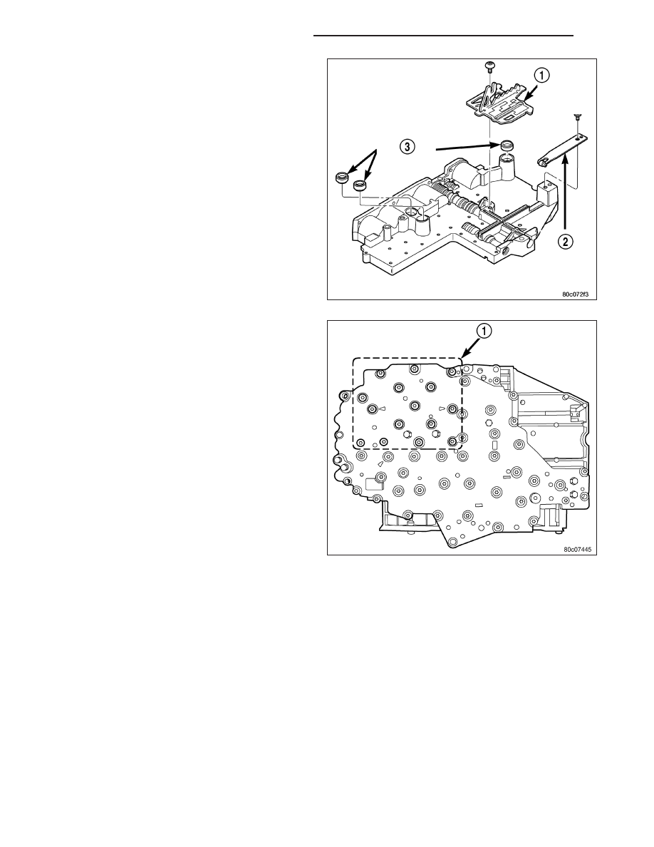
10. Install the TRS selector plate (1) onto the valve

body and the manual valve.

11. Position the detent spring (2) onto the valve body.

12. Install the screw to hold the detent spring (2) onto

the valve body. Tighten the screw to 4.5 N·m (40
in. lbs.).

13. Install new clutch passage seals (3) onto the

valve body, if necessary.

14. Install the solenoid and pressure switch assembly

onto the valve body.

15. Install the bolts (1) to hold the solenoid and pres-

sure switch assembly onto the valve body. Tighten
the bolts to 6 N·m (50 in. lbs.). Tighten the bolts
adjacent to the arrows cast into the bottom of the
transfer plate first.

21 - 816

AUTOMATIC TRANSMISSION - 545RFE

KJ

INSTALLATION

1. Check condition of seals on valve body and the

solenoid and pressure switch assembly. Replace
seals if cut or worn.

2. Place TRS selector plate in the PARK position.

3. Place the transmission in the PARK position.

4. Lubricate seal on the solenoid and pressure switch

assembly connector with petroleum jelly.

5. Position valve body in transmission and align the

manual lever on the valve body to the pin on the
transmission manual shift lever.

6. Seat valve body in case and install one or two

bolts to hold valve body in place.

7. Tighten valve body bolts alternately and evenly to

12 N·m (105 in. lbs.) torque.

CAUTION: The primary oil filter seal MUST be fully
installed flush against the oil pump body. DO NOT
install the seal onto the filter neck and attempt to
install the filter and seal as an assembly. Damage
to the transmission will result.

8. Install a new primary oil filter seal in the oil pump

inlet bore. Seat the seal in the bore with the butt
end of a hammer, or other suitable tool.

9. Place replacement filter (1) in position on valve

body and into the oil pump.

10. Install screw to hold filter to valve body. Tighten

screw to 4.5 N·m (40 in. lbs.) torque.

11. Connect the solenoid and pressure switch assem-

bly connector.

12. Install oil pan. Tighten pan bolts to 12 N·m (105 in. lbs.) torque.

13. Lower vehicle and fill transmission with Mopar

T

ATF +4.

14. Check and adjust gearshift cable, if necessary.

KJ

AUTOMATIC TRANSMISSION - 545RFE

21 - 817

TRANSFER CASE - NV231

TABLE OF CONTENTS

page

page

TRANSFER CASE - NV231

DESCRIPTION . . . . . . . . . . . . . . . . . . . . . . . . . . . . . . . 819
OPERATION . . . . . . . . . . . . . . . . . . . . . . . . . . . . . . . . . 819
DIAGNOSIS AND TESTING - TRANSFER

CASE - NV231 . . . . . . . . . . . . . . . . . . . . . . . . . . . . . 820

REMOVAL . . . . . . . . . . . . . . . . . . . . . . . . . . . . . . . . . . . 821
DISASSEMBLY . . . . . . . . . . . . . . . . . . . . . . . . . . . . . . 822
CLEANING . . . . . . . . . . . . . . . . . . . . . . . . . . . . . . . . . . 833
INSPECTION . . . . . . . . . . . . . . . . . . . . . . . . . . . . . . . . 833
ASSEMBLY . . . . . . . . . . . . . . . . . . . . . . . . . . . . . . . . . . 837
INSTALLATION . . . . . . . . . . . . . . . . . . . . . . . . . . . . . . 850
SPECIFICATIONS

TRANSFER CASE - NV231 . . . . . . . . . . . . . . . . . 851

SPECIAL TOOLS

TRANSFER CASE - NV231 . . . . . . . . . . . . . . . . . 852

FLUID

STANDARD PROCEDURE - FLUID DRAIN AND

FILL . . . . . . . . . . . . . . . . . . . . . . . . . . . . . . . . . . . . . . 854

SEAL-FRONT OUTPUT SHAFT

REMOVAL . . . . . . . . . . . . . . . . . . . . . . . . . . . . . . . . . . . 855
INSTALLATION . . . . . . . . . . . . . . . . . . . . . . . . . . . . . . 855

SENSOR-POSITION

DESCRIPTION . . . . . . . . . . . . . . . . . . . . . . . . . . . . . . . 856
OPERATION . . . . . . . . . . . . . . . . . . . . . . . . . . . . . . . . . 856
REMOVAL . . . . . . . . . . . . . . . . . . . . . . . . . . . . . . . . . . . 857
INSTALLATION . . . . . . . . . . . . . . . . . . . . . . . . . . . . . . 857

SEAL-REAR OUTPUT SHAFT

REMOVAL . . . . . . . . . . . . . . . . . . . . . . . . . . . . . . . . . . . 858
INSTALLATION . . . . . . . . . . . . . . . . . . . . . . . . . . . . . . 859

LEVER-SHIFT

REMOVAL . . . . . . . . . . . . . . . . . . . . . . . . . . . . . . . . . . . 860
INSTALLATION . . . . . . . . . . . . . . . . . . . . . . . . . . . . . . 860

21 - 818

TRANSFER CASE - NV231

KJ

TRANSFER CASE - NV231

DESCRIPTION

The NV231 is a part-time transfer case with a low range reduction gear system. The NV231 has three operating
ranges plus a NEUTRAL position. A low range system provides a reduction ratio for increased low speed torque
capability.

The geartrain is mounted in two aluminum case halves attached with bolts. The mainshaft front and rear bearings
are mounted in aluminum retainer housings bolted to the case halves.

OPERATING RANGES

Transfer case operating ranges are:

2WD (2-wheel drive)

4Hi (4-wheel drive)

4 Lo (4-wheel drive low range)

The 2WD range is for use on any road surface at any time.

The 4Hi and 4 Lo ranges are for off road use only. They are not for use on hard surface roads. The only exception
being when the road surface is wet or slippery or covered by ice and snow.

The low range reduction gear system is operative in 4 Lo range only. This range is for extra pulling power in off road
situations. Low range reduction ratio is 2.72:1.

SHIFT MECHANISM

Operating ranges are selected with a floor mounted shift lever. The shift lever is connected to the transfer case
range lever by a shift cable. A straight line shift pattern is used. Range positions are marked on the shifter knob
bezel.

IDENTIFICATION

A circular ID tag (1) is attached to the rear case of
each transfer case. The ID tag provides the transfer
case model number, assembly number, serial number,
and low range ratio.

The transfer case serial number also represents the
date of build.

OPERATION

The input gear is splined to the transmission output shaft. The input gear drives the mainshaft through the planetary
assembly and range hub. The front output shaft is operated by a drive chain that connects the shaft to a drive
sprocket on the mainshaft. The drive sprocket is engaged/disengaged by the mode fork, which operates the mode
sleeve and hub. The sleeve and hub are not equipped with a synchronizer mechanism for shifting.

KJ

TRANSFER CASE - NV231

21 - 819


Content   ..  1216  1217  1218  1219   ..