Jeep Liberty KJ. Manual - part 1214


  Index      Jeep     Jeep Liberty KJ - service repair manual 2006 year


Search            


Content   ..  1212  1213  1214  1215   ..


Jeep Liberty KJ. Manual - part 1214


1. Lubricate oil pump seal lip with transmission fluid.

2. Place torque converter in position on transmission.

CAUTION: Do not damage oil pump seal or con-
verter hub o-ring while inserting torque converter
into the front of the transmission.

3. Align torque converter to oil pump seal opening.

4. Insert torque converter hub into oil pump.

5. While pushing torque converter inward, rotate con-

verter until converter is fully seated in the oil pump
gears.

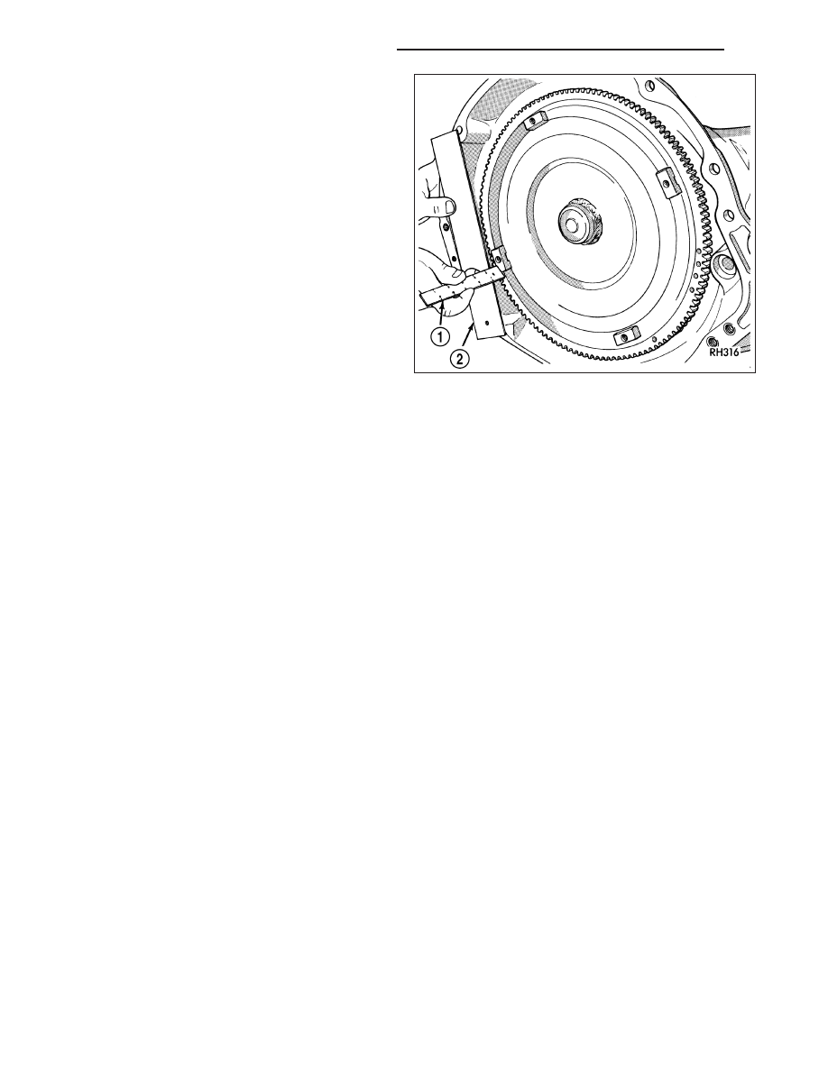
6. Check converter seating with a scale (1) and

straightedge (2). Surface of converter lugs should
be at least 13 mm (1/2 in.) to rear of straightedge
when converter is fully seated.

7. If necessary, temporarily secure converter with

C-clamp attached to the converter housing.

8. Install the transmission in the vehicle.

9. Fill the transmission with the recommended fluid.

21 - 800

AUTOMATIC TRANSMISSION - 545RFE

KJ

RELAY-TRANSMISSION CONTROL

DESCRIPTION

The relay is supplied fused B+ voltage, energized by the TCM, and is used to supply power to the solenoid pack
when the transmission is in normal operating mode.

OPERATION

When the relay is “off”, no power is supplied to the solenoid pack and the transmission is in “limp-in” mode. After a
controller reset, the TCM energizes the relay. Prior to this, the TCM verifies that the contacts are open by checking
for no voltage at the switched battery terminals. After this is verified, the voltage at the solenoid pack pressure
switches is checked. After the relay is energized, the TCM monitors the terminals to verify that the voltage is greater
than 3 volts.

KJ

AUTOMATIC TRANSMISSION - 545RFE

21 - 801

SENSOR-TRANSMISSION RANGE

DESCRIPTION

The Transmission Range Sensor (TRS) is part of the solenoid module, which is mounted to the top of the valve
body inside the transmission.

The Transmission Range Sensor (TRS) has five switch contact pins that:

Determine shift lever position

Supply ground to the Starter Relay in Park and Neutral only.

Supply +12 V to the backup lamps in Reverse only.

The TRS also has an integrated temperature sensor (thermistor) that communicates transmission temperature to the
TCM and PCM.

OPERATION

The Transmission Range Sensor (TRS) communicates shift lever position to the TCM as a combination of open and
closed switches. Each shift lever position has an assigned combination of switch states (open/closed) that the TCM
receives from four sense circuits. The TCM interprets this information and determines the appropriate transmission
gear position and shift schedule.

There are many possible combinations of open and closed switches (codes). Seven of these possible codes are
related to gear position and five are recognized as “between gear” codes. This results in many codes which should
never occur. These are called “invalid” codes. An invalid code will result in a DTC, and the TCM will then determine
the shift lever position based on pressure switch data. This allows reasonably normal transmission operation with a
TRS failure.

GEAR

C5

C4

C3

C2

C1

Park

CL

OP

OP

CL

CL

Temp 1

CL

OP

OP

CL

OP

Reverse

OP

OP

OP

CL

OP

Temp 2

OP

OP

CL

CL

OP

Neutral 1

OP

OP

CL

CL

CL

Neutral 2

OP

CL

CL

CL

CL

Temp 3

OP

CL

CL

CL

OP

Drive

OP

CL

CL

OP

OP

Temp 4

OP

CL

OP

OP

OP

Manual 2

CL

CL

OP

OP

OP

Temp 5

CL

OP

OP

OP

OP

Manual 1

CL

OP

CL

OP

OP

21 - 802

AUTOMATIC TRANSMISSION - 545RFE

KJ

ASSEMBLY-TRANSMISSION SOLENOID/TRS

DESCRIPTION

The transmission solenoid/TRS assembly is internal to
the transmission and mounted on the valve body
assembly. The assembly consists of six solenoids that
control hydraulic pressure to the six friction elements
(transmission clutches), and the torque converter
clutch. The pressure control solenoid is located on the
side of the solenoid/TRS assembly. The solenoid/TRS
assembly also contains five pressure switches that
feed information to the TCM.

OPERATION

SOLENOIDS

Solenoids are used to control the L/R, 2C, 4C, OD, and UD friction elements. The reverse clutch is controlled by
line pressure and the position of the manual valve in the valve body. All the solenoids are contained within the
Solenoid and Pressure Switch Assembly. The solenoid and pressure switch assembly contains one additional sole-
noid, Multi-Select (MS), which serves primarily to provide 2nd and 3rd gear limp-in operation.

The solenoids receive electrical power from the Transmission Control Relay through a single wire. The TCM ener-
gizes or operates the solenoids individually by grounding the return wire of the solenoid as necessary. When a
solenoid is energized, the solenoid valve shifts, and a fluid passage is opened or closed (vented or applied),
depending on its default operating state. The result is an apply or release of a frictional element.

The MS and UD solenoids are normally applied to allow transmission limp-in in the event of an electrical failure.

The continuity of the solenoids and circuits are periodically tested. Each solenoid is turned on or off depending on
its current state. An inductive spike should be detected by the TCM during this test. If no spike is detected, the
circuit is tested again to verify the failure. In addition to the periodic testing, the solenoid circuits are tested if a
speed ratio or pressure switch error occurs.

PRESSURE SWITCHES

The TCM relies on five pressure switches to monitor fluid pressure in the L/R, 2C, 4C, UD, and OD hydraulic cir-
cuits. The primary purpose of these switches is to help the TCM detect when clutch circuit hydraulic failures occur.
The switches close at approximately 23 psi and open at approximately 11 psi, and simply indicate whether or not
pressure exists. The switches are continuously monitored by the TCM for the correct states (open or closed) in each
gear as shown in the following chart:

GEAR

L/R

2C

4C

UD

OD

R

OP

OP

OP

OP

OP

P/N

CL

OP

OP

OP

OP

1ST

CL*

OP

OP

CL

OP

2ND

OP

CL

OP

CL

OP

2ND PRIME

OP

OP

CL

CL

OP

KJ

AUTOMATIC TRANSMISSION - 545RFE

21 - 803


Content   ..  1212  1213  1214  1215   ..