Jeep Liberty KJ. Manual - part 1178


  Index      Jeep     Jeep Liberty KJ - service repair manual 2006 year


Search            


Content   ..  1176  1177  1178  1179   ..


Jeep Liberty KJ. Manual - part 1178


5.

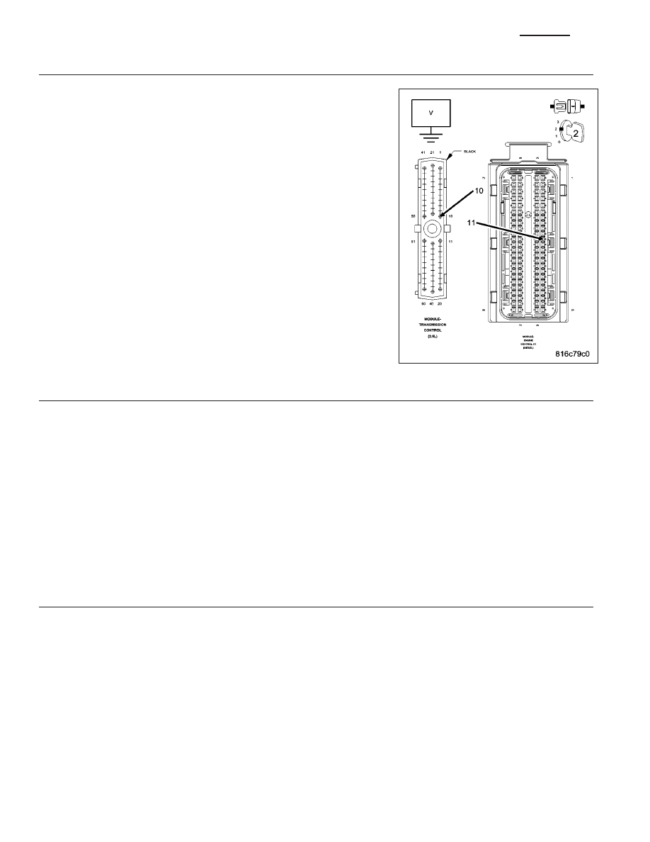
TORQUE MANAGEMENT REQUEST SENSE CIRCUIT SHORT TO VOLTAGE

Turn the ignition on.

Measure the voltage of the Torque Management Request Sense circuit
in the TCM harness connector.

Is the voltage above 10.5 volts?

Yes

>> Repair the Torque Management Request Sense circuit for a

short to voltage.

Perform 45RFE/545RFE TRANSMISSION VERIFICATION
TEST - VER 1. (Refer to 21 - TRANSMISSION/TRANS-
AXLE/AUTOMATIC - 45RFE/545RFE - STANDARD PRO-
CEDURE)

No

>> Go To 6

6.

TRANSMISSION CONTROL MODULE

Measure the voltage of the Torque Management Request Sense circuit in the TCM harness connector.

Is the voltage above 7.0 volts?

Yes

>> Using the schematics as a guide, check the Transmission Control Module (TCM) terminals for corrosion,

damage, or terminal push out. Pay particular attention to all power and ground circuits. If no problems
are found, replace the TCM per the Service Information. With the scan tool, perform QUICK LEARN.

Perform 45RFE/545RFE TRANSMISSION VERIFICATION TEST - VER 1. (Refer to 21 - TRANSMIS-
SION/TRANSAXLE/AUTOMATIC - 45RFE/545RFE - STANDARD PROCEDURE)

No

>> Using the schematics as a guide, check the Powertrain Control Module (ECM) terminals for corrosion,

damage, or terminal push out. Pay particular attention to all power and ground circuits. If no problems
are found, replace the ECM per the Service Information. With the scan tool, perform QUICK LEARN.

Perform 45RFE/545RFE TRANSMISSION VERIFICATION TEST - VER 1. (Refer to 21 - TRANSMIS-
SION/TRANSAXLE/AUTOMATIC - 45RFE/545RFE - STANDARD PROCEDURE)

7.

INTERMITTENT WIRING AND CONNECTORS

The conditions necessary to set this DTC are not present at this time.

Using the schematics as a guide, inspect the wiring and connectors specific to this circuit.

Wiggle the wires while checking for shorted and open circuits.

This DTC can also be set by the Solenoid Switch Valve intermittently sticking in it’s bore under extreme temperature
conditions, or by a worn Solenoid Switch Valve or plugs.

With the scan tool, check the DTC EVENT DATA to help identify the conditions in which the DTC was set.

Where there any problems found?

Yes

>> Repair as necessary.

Perform 45RFE/545RFE TRANSMISSION VERIFICATION TEST - VER 1. (Refer to 21 - TRANSMIS-
SION/TRANSAXLE/AUTOMATIC - 45RFE/545RFE - STANDARD PROCEDURE)

No

>> Test Complete.

21 - 656

AUTOMATIC TRANSMISSION 545RFE - ELECTRICAL DIAGNOSTICS - (DIESEL)

KJ

P1794-SPEED SENSOR GROUND ERROR

For a complete wiring diagram Refer to Section 8W

KJ

AUTOMATIC TRANSMISSION 545RFE - ELECTRICAL DIAGNOSTICS - (DIESEL)

21 - 657

When Monitored:
The gear ratio is monitored continuously while the Transmission is in gear.

Set Condition:
After a controller reset in neutral and a ratio of input to output, of 1 to 2. This DTC can take up to five minutes
of problem identification before illuminating the MIL.

Possible Causes

(T13) SPEED SENSOR GROUND CIRCUIT OPEN

(T13) SPEED SENSOR GROUND CIRCUIT SHORT TO GROUND

(T13) SPEED SENSOR GROUND CIRCUIT SHORT TO VOLTAGE

TRANSMISSION CONTROL MODULE

Always perform the 45RFE/545RFE Pre-Diagnostic Troubleshooting procedure before proceeding. (Refer to
21 - TRANSMISSION/TRANSAXLE/AUTOMATIC - 45RFE/545RFE - STANDARD PROCEDURE)

Theory of Operation

The transmission system uses two speed sensors, one to measure input RPM and one to measure output RPM.
These inputs are essential for proper transmission operation. Therefore, the integrity of this data is verified through
the following checks:

1) When in gear, if the gear ratio does not compare to a known gear ratio, the corresponding in-gear trouble code
is set (DTCs P0731–36).

2) An excessive change in input or output speeds indicating signal intermittent which may result in the DTCs P0715
and/or P0720 to set.

3) If the common speed sensor ground circuit is lost, both sensor inputs will read the signal from the input speed
sensor at idle in neutral. Since the input speed sensor reads 60 teeth from the input clutch hub and the output
speed sensor reads 30 teeth from the park gear, the result is an apparent speed ratio of 1:2 and may cause the
DTC P1794 to set when at a stop.

Diagnostic Test

1.

CHECK TO SEE IF DTC P1794 IS CURRENT

Engine Running, Shift lever in park.

With the scan tool, read the Transmission Output and Input Speed Sensor states.

Is the Output Speed Sensor reading twice the Input Speed Sensor reading?

Yes

>> Go To 2

No

>> Go To 6

2.

TCM AND WIRING

Turn the ignition off to the lock position.

Remove the Starter Relay.

CAUTION: Removal of the Starter Relay will prevent the vehicle from being started in gear.

WARNING: The Starter Relay must be removed from the PDC. Failure to do so can result in personal injury
or death.

NOTE: Failure to remove the Starter Relay can cause a Transmission - No Response condition.
Install the Transmission Simulator, Miller tool 8333.

With the Transmission Simulator, set the Input/Output Speed selector switch to the

9

3000/1000

9

position. Turn the

Input/Output Speed switch to

9

ON

9

.

Ignition on, engine not running.

21 - 658

AUTOMATIC TRANSMISSION 545RFE - ELECTRICAL DIAGNOSTICS - (DIESEL)

KJ

With the scan tool, monitor the Input and Output Speed Sensor state.

Does the Input speed read 3000 RPM and the Output speed read 1000 RPM, within 50 RPM?

Yes

>> Go To 6

No

>> Go To 3

3.

(T13) SPEED SENSOR GROUND CIRCUIT OPEN

Turn the ignition off to the lock position.

Disconnect the TCM harness connector.

Disconnect the Transmission Simulator, Miller tool #8333.

Measure the resistance of the (T13) Speed Sensor Ground circuit from
the appropriate terminal of the TCM harness connector to the Transmis-
sion Solenoid/TRS Assembly and both Input and Output Speed Sensor
harness connectors.

Is the resistance above 5.0 ohms on any of the above mea-
surements?

Yes

>> Repair the (T13) Speed Sensor Ground circuit for an open.

Perform 45RFE/545RFE TRANSMISSION VERIFICATION
TEST - VER 1. (Refer to 21 - TRANSMISSION/TRANS-
AXLE/AUTOMATIC - 45RFE/545RFE - STANDARD PRO-
CEDURE)

No

>> Go To 4

4.

(T13) SPEED SENSOR GROUND CIRCUIT SHORT TO GROUND

Measure the resistance between ground and the (T13) Speed Sensor
Ground circuit.

Is the resistance below 5.0 ohms?

Yes

>> Repair the (T13) Speed Sensor Ground circuit for a short to

ground.

Perform 45RFE/545RFE TRANSMISSION VERIFICATION
TEST - VER 1. (Refer to 21 - TRANSMISSION/TRANS-
AXLE/AUTOMATIC - 45RFE/545RFE - STANDARD PRO-
CEDURE)

No

>> Go To 5

KJ

AUTOMATIC TRANSMISSION 545RFE - ELECTRICAL DIAGNOSTICS - (DIESEL)

21 - 659


Content   ..  1176  1177  1178  1179   ..