Content .. 1086 1087 1088 1089 ..
Jeep Liberty KJ. Manual - part 1088
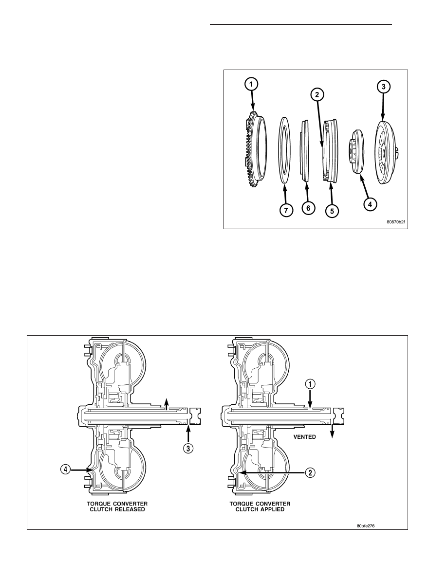
TORQUE CONVERTER CLUTCH (TCC)
The TCC was installed to improve the efficiency of the
torque converter that is lost to the slippage of the fluid
coupling. Although the fluid coupling provides smooth,
shock-free power transfer, it is natural for all fluid cou-
plings to slip. If the impeller (3) and turbine (5) were
mechanically locked together, a zero slippage condi-
tion could be obtained. A hydraulic piston (6) with fric-
tion material (7) was added to the turbine assembly
(5) to provide this mechanical lock-up.
In order to reduce heat build-up in the transmission
and buffer the powertrain against torsional vibrations,
the TCM can duty cycle the L/R-CC Solenoid to
achieve a smooth application of the torque converter
clutch. This function, referred to as Electronically Mod-
ulated Converter Clutch (EMCC) can occur at various
times depending on the following variables:
•
Shift lever position
•
Current gear range
•
Transmission fluid temperature
•
Engine coolant temperature
•
Input speed
•
Throttle angle
•
Engine speed
OPERATION
The converter impeller (driving member), which is integral to the converter housing and bolted to the engine drive
plate, rotates at engine speed. The converter turbine (driven member), which reacts from fluid pressure generated
by the impeller, rotates and turns the transmission input shaft.
21 - 396
AUTOMATIC TRANSMISSION - 42RLE
KJ