Jeep Liberty KJ. Manual - part 99


  Index      Jeep     Jeep Liberty KJ - service repair manual 2006 year


Search            


Content   ..  97  98  99  100   ..


Jeep Liberty KJ. Manual - part 99


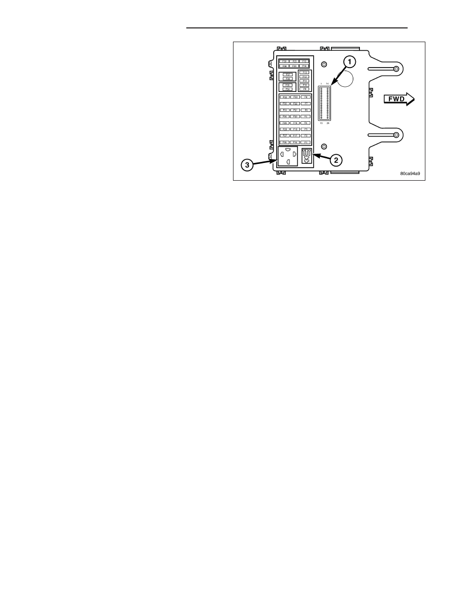
1. Position the Daytime Running Lamp (DRL) relay to

the proper receptacle (3) in the JB. The adjacent
receptacle (2) must NOT be populated by a head-
lamp high beam relay on a vehicle that is equipped
with a DRL relay.

2. Align the DRL relay terminals with the cavities in

the JB receptacle.

3. Push firmly and evenly on the top of the DRL relay

until the relay base is fully seated in the JB recep-
tacle.

4. Reinstall the trim onto the driver side outboard end

of the instrument panel. (Refer to 23 - BODY/IN-
STRUMENT PANEL/INSTRUMENT PANEL END
CAP - INSTALLATION).

5. Reconnect the battery negative cable.

8L - 54

LAMPS/LIGHTING - EXTERIOR

KJ

FOG LAMP RELAY

DESCRIPTION

FRONT

The front fog lamp relay is a conventional International
Standards Organization (ISO) micro relay. Relays con-
forming to the ISO specifications have common phys-
ical dimensions, current capacities, terminal patterns,
and terminal functions. This relay is contained within a
small, rectangular, molded plastic housing and is con-
nected to all of the required inputs and outputs
through five integral male spade-type terminals that
extend from the relay base plate.

The front fog lamp relay is located in the Junction Block (JB) on the driver side outboard end bracket of the instru-
ment panel. Refer to Junction Block in the wiring section of this service information for specific relay cavity assign-
ment information. The front fog lamp relay cannot be adjusted or repaired and, if inoperative or damaged, the unit
must be replaced.

REAR

The rear fog lamp relay is a conventional International
Standards Organization (ISO) micro relay. Relays con-
forming to the ISO specifications have common phys-
ical dimensions, current capacities, terminal patterns,
and terminal functions. This relay is contained within a
small, rectangular, molded plastic housing and is con-
nected to all of the required inputs and outputs
through five integral male spade-type terminals that
extend from the relay base plate.

The rear fog lamp relay is located in the Junction Block (JB) on the driver side outboard end bracket of the instru-
ment panel. Refer to Junction Block in the wiring section of this service information for specific relay cavity assign-
ment information. The rear fog lamp relay cannot be adjusted or repaired and, if inoperative or damaged, the unit
must be replaced.

KJ

LAMPS/LIGHTING - EXTERIOR

8L - 55

OPERATION

FRONT

The front fog lamp relay is an electromechanical switch that uses a low current input from the Body Control Module
(BCM) to control a high current output to the front fog lamps. Within the relay are an electromagnetic coil, a mov-
able contact and two fixed contact points. A resistor is connected in parallel with the coil, and helps to dissipate
voltage spikes and electromagnetic interference that can be generated as the field of the relay coil collapses.

The movable common supply contact point is held against the fixed normally closed contact point by spring pres-
sure. When the relay coil is energized, an electromagnetic field is produced by the coil windings. This field draws
the movable contact point away from the normally closed contact, and holds it against the normally open contact.
When the relay coil is de-energized, spring pressure returns the movable contact back against the normally closed
contact.

The inputs and outputs of the front fog lamp relay include:

Common Supply Terminal (30) - The common feed terminal is connected to a fused B(+) circuit at all times.

Coil Ground Terminal (85) - The coil ground terminal is connected to a control output of the premium Body
Control Module (BCM) through a front fog lamp relay control circuit. The BCM controls front fog lamp operation
by controlling a ground path through this circuit.

Coil Battery Terminal (86) - The coil battery terminal is connected to a fused B(+) circuit at all times.

Normally Open Terminal (87) - The normally open terminal is connected to the front fog lamps through a front
fog lamp relay output circuit and provides battery voltage to the front fog lamps whenever the relay is ener-
gized.

Normally Closed Terminal (87A) - The normally closed terminal is not connected in this application, but will
have battery voltage present whenever the relay is de-energized.

The front fog lamp relay can be diagnosed using conventional diagnostic tools and methods. Refer to the appro-
priate wiring information.

REAR

The rear fog lamp relay is an electromechanical switch that uses a low current input from the Body Control Module
(BCM) to control a high current output to the rear fog lamps. Within the relay are an electromagnetic coil, a movable
contact and two fixed contact points. A resistor is connected in parallel with the coil, and helps to dissipate voltage
spikes and electromagnetic interference that can be generated as the field of the relay coil collapses.

The movable common supply contact point is held against the fixed normally closed contact point by spring pres-
sure. When the relay coil is energized, an electromagnetic field is produced by the coil windings. This field draws
the movable contact point away from the normally closed contact, and holds it against the normally open contact.
When the relay coil is de-energized, spring pressure returns the movable contact back against the normally closed
contact.

The inputs and outputs of the rear fog lamp relay include:

Common Supply Terminal (30) - The common feed terminal is connected to a fused B(+) circuit at all times.

Coil Ground Terminal (85) - The coil ground terminal is connected to a control output of the premium BCM
through a rear fog lamp relay control circuit. The BCM controls rear fog lamp operation by controlling a ground
path through this circuit.

Coil Battery Terminal (86) - The coil battery terminal is connected to a fused B(+) circuit at all times.

Normally Open Terminal (87) - The normally open terminal is connected to the rear fog lamps through a rear
fog lamp relay output circuit and provides battery voltage to the rear fog lamps whenever the relay is ener-
gized.

Normally Closed Terminal (87A) - The normally closed terminal is not connected in this application, but will
have battery voltage present whenever the relay is de-energized.

The rear fog lamp relay can be diagnosed using conventional diagnostic tools and methods. Refer to the appropri-
ate wiring information.

8L - 56

LAMPS/LIGHTING - EXTERIOR

KJ

FRONT FOG LAMP

REMOVAL

BULB - GRILLE MOUNTED

CAUTION: Do not contaminate the bulb glass by touching it with your fingers or by allowing it to contact
other oily surfaces. Shortened bulb life will result.

1. Disconnect and isolate the battery negative cable.

2. Remove the front fog lamp from the grille opening

reinforcement (1), but do not disconnect the wire
harness connector (3) from the socket (2) on the
back of the lamp housing (4). (Refer to 8 - ELEC-
TRICAL/LAMPS/LIGHTING - EXTERIOR/FRONT
FOG LAMP - REMOVAL).

3. Firmly grasp the socket on the back of the housing

and rotate it counterclockwise about 30 degrees to
unlock it.

4. Pull the socket and bulb straight out from the

keyed opening in the housing.

5. Pull the base of the bulb straight out of the socket.

BULB - FASCIA MOUNTED

CAUTION: Do not contaminate the bulb glass by touching it with your fingers or by allowing it to contact
other oily surfaces. Shortened bulb life will result.

1. Disconnect and isolate the battery negative cable.

2. Remove the three screws (2) that secure the front

fog lamp bezel and lens to the back of the lamp
housing (1).

KJ

LAMPS/LIGHTING - EXTERIOR

8L - 57


Content   ..  97  98  99  100   ..