Jeep Liberty KJ. Manual - part 47
CYLINDER-KEY/LOCK
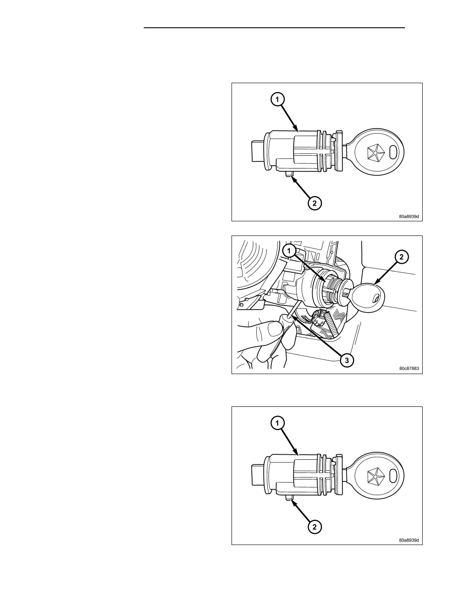
REMOVAL
The ignition key must be in the key cylinder (1) for cyl-
inder removal. The key cylinder must be removed first
before removing ignition switch.
1. If equipped with an automatic transmission, place
shifter in PARK position.
2. Remove the lower shroud cover.
3. Remove the remote keyless entry (R.K.E.) module.
4. Remove the halo ring around the cylinder.
5. Rotate key to ON position.
6. A release tang (2) is located on bottom of key cyl-
inder (1).
7. Position a small screwdriver or pin punch (3) into
tang access hole on bottom of steering column.
8. Push the pin punch (3) up while pulling key cylin-
der (1) from steering column.
INSTALLATION
The ignition key must be in the key cylinder (1) for cyl-
inder installation.
1. Install the key cylinder (1) into the housing using
care to align the end of the key cylinder with the
ignition switch.
2. Push the key cylinder (1) in until it clicks .
3. Rotate the key to the insert position.
4. install the halo ring around the key cylinder hous-
ing.
5. Install the R.K.E. module.
6. Install the lower shroud cover.
8I - 20
IGNITION CONTROL
KJ