Jeep Grand Cherokee WK. Manual - part 994
P0521-ENGINE OIL PRESSURE SENSOR PERFORMANCE (CONTINUED)
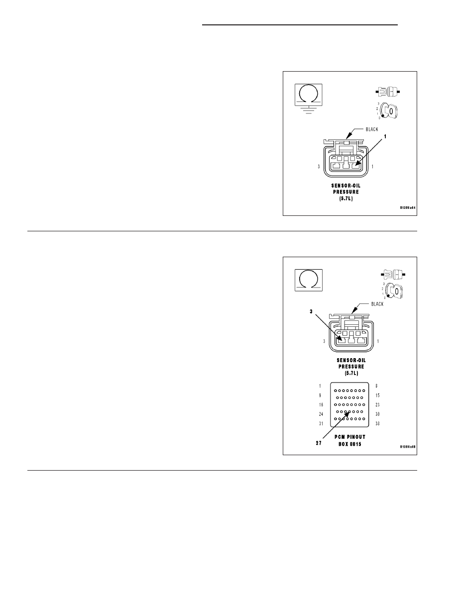
8.
(F855) 5-VOLT SUPPLY SHORTED TO GROUND
Measure the resistance between ground and the (F855) 5-volt Supply
circuit in the Engine Oil Pressure Sensor harness connector.
Is the resistance below 100 ohms?
Yes
>> Repair the short to ground in the (F855) 5-volt Supply cir-
cuit.
Perform the POWERTRAIN VERIFICATION TEST. (Refer
to 9 - ENGINE - STANDARD PROCEDURE)
No
>> Go To 9
9.
EXCESSIVE RESISTANCE IN THE (K900) SENSOR GROUND CIRCUIT
Measure the resistance of the (K900) Sensor Ground circuit from the
Engine Oil Pressure Sensor harness connector to the appropriate ter-
minal of special tool #8815.
Is the resistance below 5.0 ohms?
Yes
>> Go To 10
No
>> Repair the excessive resistance in the (K900) Sensor
Ground circuit.
Perform the POWERTRAIN VERIFICATION TEST. (Refer
to 9 - ENGINE - STANDARD PROCEDURE)
9 - 572
ENGINE ELECTRICAL DIAGNOSTICS
WK