Index Jeep Jeep Grand Cherokee WK - service repair manual 2005 year
Search
Content .. 960 961 962 963 ..
Jeep Grand Cherokee WK. Manual - part 962
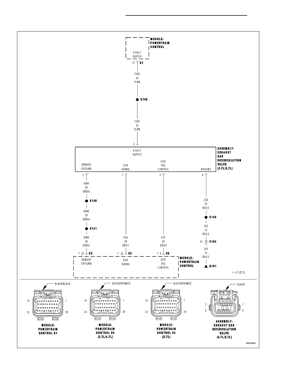
P0401-EGR SYSTEM PERFORMANCE
9 - 444
ENGINE ELECTRICAL DIAGNOSTICS
WK