Jeep Grand Cherokee WK. Manual - part 666


  Index      Jeep     Jeep Grand Cherokee WK - service repair manual 2005 year


Search            


Content   ..  664  665  666  667   ..


Jeep Grand Cherokee WK. Manual - part 666


SEAT BELT TURNING LOOP ADJUSTER

REMOVAL

WARNING: To avoid personal injury or death, during and following any seat belt or child restraint anchor
service, carefully inspect all seat belts, buckles, mounting hardware, retractors, tether straps, and anchors
for proper installation, operation, or damage. Replace any belt that is cut, frayed, or torn. Straighten any
belt that is twisted. Tighten any loose fasteners. Replace any belt that has a damaged or inoperative buckle
or retractor. Replace any belt that has a bent or damaged latch plate or anchor plate. Replace any child
restraint anchor or the unit to which the anchor is integral that has been bent or damaged. Never attempt to
repair a seat belt or child restraint component. Always replace damaged or faulty seat belt and child
restraint components with the correct, new and unused replacement parts listed in the DaimlerChrysler
Mopar Parts Catalog.

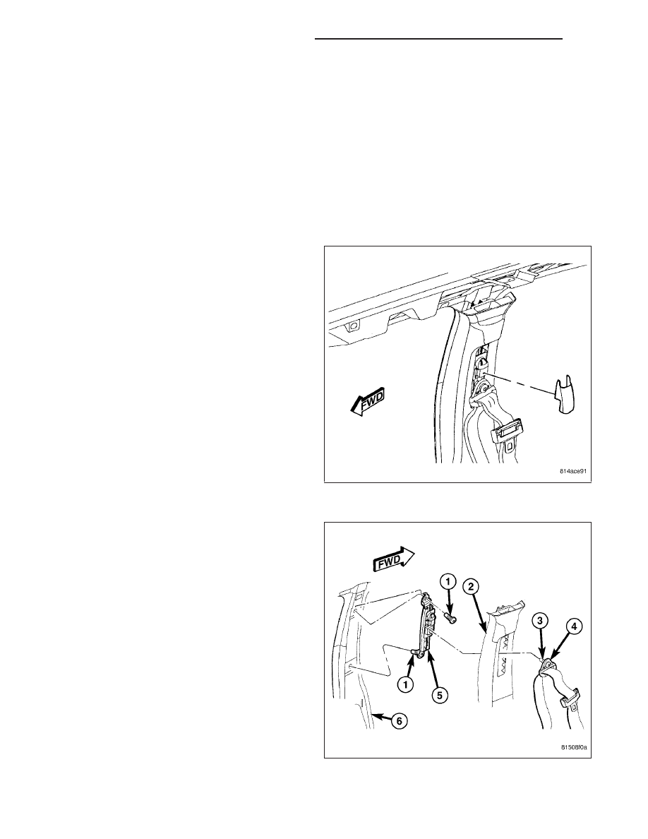
1. Firmly grasp the lower end of the turning loop trim

cover on the upper B-pillar and pull it straight out to
unsnap it from the height adjuster, then lift the bot-
tom of the cover upward and pull outward to disen-
gage the upper tabs from the adjuster.

2. Remove the screw (3) that secures the seat belt

turning loop (4) to the height adjuster (5).

3. Remove the seat belt turning loop from the height

adjuster.

4. Remove the upper trim (2) from the inside of the

B-pillar (6). (Refer to 23 - BODY/INTERIOR/B-PIL-
LAR UPPER TRIM - REMOVAL).

5. Remove the two screws (1) that secure the height

adjuster to the inside of the B-pillar.

6. Remove the adjuster from the B-pillar.

8O - 486

RESTRAINTS - SERVICE INFORMATION

WK

INSTALLATION

WARNING: To avoid personal injury or death, during and following any seat belt or child restraint anchor
service, carefully inspect all seat belts, buckles, mounting hardware, retractors, tether straps, and anchors
for proper installation, operation, or damage. Replace any belt that is cut, frayed, or torn. Straighten any
belt that is twisted. Tighten any loose fasteners. Replace any belt that has a damaged or inoperative buckle
or retractor. Replace any belt that has a bent or damaged latch plate or anchor plate. Replace any child
restraint anchor or the unit to which the anchor is integral that has been bent or damaged. Never attempt to
repair a seat belt or child restraint component. Always replace damaged or faulty seat belt and child
restraint components with the correct, new and unused replacement parts listed in the DaimlerChrysler
Mopar Parts Catalog.

1. Position the seat belt turning loop adjuster (5) to

the inside of the B-pillar (6).

2. Install and tighten the two screws (1) that secure

the adjuster to the B-pillar. Tighten the screws to
39 N·m (29 ft. lbs.).

3. Reinstall the upper trim (2) onto the inside of the

B-pillar. (Refer to 23 - BODY/INTERIOR/B-PILLAR
UPPER TRIM - INSTALLATION).

4. Position the seat belt turning loop (4) onto the

height adjuster on the upper B-pillar. Be certain
that the seat belt webbing between the retractor
and the turning loop is not twisted.

5. Install and tighten the screw (3) that secures the

turning loop to the height adjuster. Tighten the
screw to 39 N·m (29 ft. lbs.).

6. Insert the upper tabs of the turning loop trim cover

into the slots of the height adjuster on the upper
B-pillar, then lower the bottom of the cover and use
hand pressure to press firmly and evenly on the
cover until it snaps into place.

WK

RESTRAINTS - SERVICE INFORMATION

8O - 487

SEAT TRACK POSITION SENSOR

DESCRIPTION

The seat track position sensor (1) is a Hall Effect-type
sensor. This sensor consists of a Hall Effect Integrated
Circuit (IC) chip encased in potting material within a
cavity of the molded plastic sensor housing. The sen-
sor housing has an integral snap feature (3) and
snaps into a stamped metal bracket located on the
inboard side of one of the seat adjuster tracks on
each front seat, then is secured by a screw into a
mounting boss (4) at one end of the sensor housing. A
molded connector receptacle (2) is integral to the
opposite end of the sensor housing from the mounting
boss is connected to the vehicle electrical system
through a connector and take out of the driver or pas-
senger seat wire harness beneath the front seat cush-
ion frame.

The seat track position sensor cannot be adjusted or
repaired and, if faulty or damaged, the entire sensor
must be replaced.

OPERATION

The seat track position sensor is designed to provide a seat position data input to the Occupant Classification Mod-
ule (OCM) indicating whether the driver front seat is in a full forward or a not full forward position. The OCM sends
electronic seat position messages to the Occupant Restraint Controller (ORC) over the Controller Area Network
(CAN) data bus. The ORC uses this data as an additional logic input for use in determining the appropriate deploy-
ment force to be used when deploying the multistage front airbags.

The seat track position sensor receives a nominal five volt supply from the OCM. The sensor communicates the
seat position by modulating the voltage returned to the OCM on a sensor data circuit. The OCM also monitors the
condition of the sensor circuits and will store a Diagnostic Trouble Code (DTC) for any fault that is detected, then
send messages to the ORC to illuminate the airbag indicator in the instrument cluster. For proper diagnosis of the
seat track position sensor, a diagnostic scan tool is required. Refer to the appropriate diagnostic information.

REMOVAL

WARNING: To avoid personal injury or death, on vehicles equipped with airbags, disable the supplemental
restraint system before attempting any steering wheel, steering column, airbag, occupant classification sys-
tem, seat belt tensioner, impact sensor, or instrument panel component diagnosis or service. Disconnect
and isolate the battery negative (ground) cable, then wait two minutes for the system capacitor to discharge
before performing further diagnosis or service. This is the only sure way to disable the supplemental
restraint system. Failure to take the proper precautions could result in accidental airbag deployment.

8O - 488

RESTRAINTS - SERVICE INFORMATION

WK

1. Disconnect and isolate the battery negative cable.

Wait two minutes for the system capacitor to dis-
charge before further service.

2. Reach under the front seat cushion to access the

seat track position sensor (3) in a bracket (5)
located on the inboard side of either the inner or
outer, driver or passenger seat track.

3. Disconnect the electrical connector (4) from the

sensor.

4. Remove the screw (1) that secures the sensor

mounting boss to the bracket.

5. Using a small screwdriver, depress the sensor latch

feature (2) and pull the sensor out of the bracket.

INSTALLATION

WARNING: To avoid personal injury or death, on vehicles equipped with airbags, disable the supplemental
restraint system before attempting any steering wheel, steering column, airbag, occupant classification sys-
tem, seat belt tensioner, impact sensor, or instrument panel component diagnosis or service. Disconnect
and isolate the battery negative (ground) cable, then wait two minutes for the system capacitor to discharge
before performing further diagnosis or service. This is the only sure way to disable the supplemental
restraint system. Failure to take the proper precautions could result in accidental airbag deployment.

1. Reach under the front seat cushion to position the

seat track position sensor (3) to the open end of
the bracket (5) located on the inboard side of either
the inner or outer, driver or passenger seat track.

2. Push the sensor firmly into the bracket until the

latch feature (2) snaps into place.

3. Install and tighten the screw (1) that secures the

sensor mounting boss to the bracket. Tighten the
screw to 2 N·m (15 in. lbs.).

4. Reconnect the seat wire harness connector (4) to

the sensor connector receptacle located on the end
of the sensor. Be certain that the latch on the con-
nector is fully engaged.

5. Do not reconnect the battery negative cable at this

time. The supplemental restraint system verification
test procedure should be performed following ser-
vice of any supplemental restraint system compo-
nent. (Refer to 8 - ELECTRICAL/RESTRAINTS -
STANDARD PROCEDURE - VERIFICATION TEST).

6. Following successful completion of the supplemental restraint system verification test procedure, perform the

Occupant Classification System Verification Test using a diagnostic scan tool. Refer to the appropriate diagnostic
procedures.

WK

RESTRAINTS - SERVICE INFORMATION

8O - 489


Content   ..  664  665  666  667   ..