Jeep Grand Cherokee WK. Manual - part 657


  Index      Jeep     Jeep Grand Cherokee WK - service repair manual 2005 year


Search            


Content   ..  655  656  657  658   ..


Jeep Grand Cherokee WK. Manual - part 657


WARNING: To avoid personal injury or death, the driver airbag trim cover must never be painted. Replace-
ment trim covers are serviced in the original colors. Paint may change the way in which the material of the
trim cover responds to an airbag deployment. Failure to observe this warning could result in occupant inju-
ries upon airbag deployment.

NOTE: The following procedures can be used to replace the driver airbag trim cover and/or to access the
horn switch unit for service. If the driver airbag is faulty or deployed, the entire driver airbag, trim cover,
and horn switch must be replaced as a unit.

1. Disconnect and isolate the battery negative cable.

Wait two minutes for the system capacitor to dis-
charge before further service.

2. Remove the driver airbag from the steering wheel.

(Refer to 8 - ELECTRICAL/RESTRAINTS/DRIVER
AIRBAG - REMOVAL).

3. Place the driver airbag on a suitable work surface

with the trim cover facing down. If the trim cover
will be reused, be certain to take the proper pre-
cautions to prevent the trim cover from receiving
cosmetic damage during the following procedures.

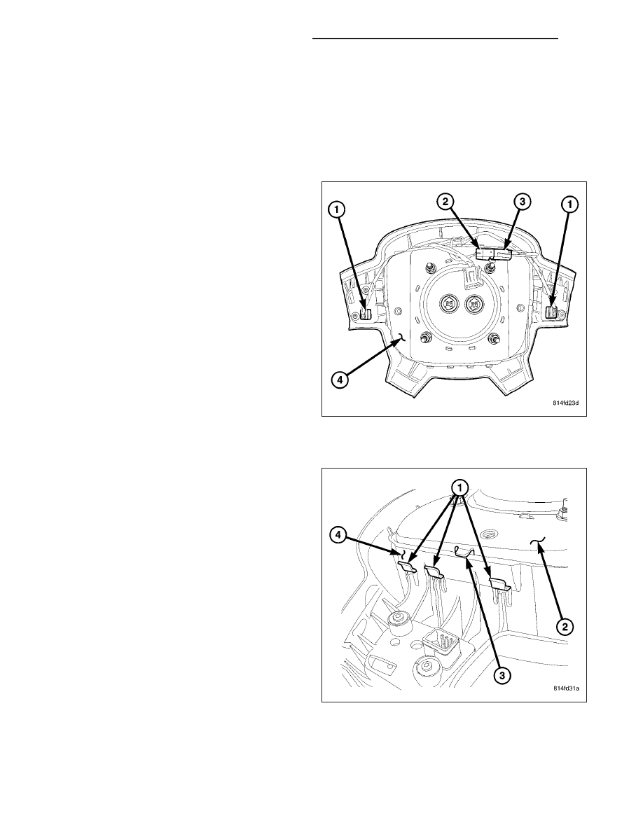
4. Disconnect the driver airbag jumper harness con-

nector (2) from the horn switch pigtail wire connec-
tor (3).

5. Carefully pry the horn switch pigtail wire connector

away from the back of the driver airbag housing (3)
far enough to disengage the integral connector
retainer from the locator hole just above the upper
left inflator mounting stud.

6. Disengage each of the fifteen hooks (1) of the air-

bag housing (2) from the fifteen windows in the
vertical walls of the trim cover (4), one wall at a
time. Start by disengaging the two side walls from
under the engagement tabs (3), and finish with the
upper and lower wall. To disengage the hooks, use
hand pressure to push the adjacent edge of the air-
bag housing firmly and evenly downward into the
trim cover receptacle, while at the same time pull-
ing outward on the upper edge of the receptacle
wall.

7. With all of the hooks disengaged, lift the housing,

inflator, cushion and horn switch as a unit from the
receptacle on the back of the driver airbag trim
cover.

8O - 450

RESTRAINTS - SERVICE INFORMATION

WK

ASSEMBLY

WARNING: To avoid personal injury or death, on vehicles equipped with airbags, disable the supplemental
restraint system before attempting any steering wheel, steering column, airbag, occupant classification sys-
tem, seat belt tensioner, impact sensor, or instrument panel component diagnosis or service. Disconnect
and isolate the battery negative (ground) cable, then wait two minutes for the system capacitor to discharge
before performing further diagnosis or service. This is the only sure way to disable the supplemental
restraint system. Failure to take the proper precautions could result in accidental airbag deployment.

WARNING: To avoid personal injury or death, service of this unit should be performed only by Daimler-
Chrysler-trained and authorized dealer service technicians. Failure to take the proper precautions or to fol-
low the proper procedures could result in accidental, incomplete, or improper airbag deployment and
possible occupant injuries.

WARNING: To avoid personal injury or death, use extreme care to prevent any foreign material from enter-
ing the driver airbag, or becoming entrapped between the driver airbag cushion and the driver airbag trim
cover. Failure to observe this warning could result in occupant injuries upon airbag deployment.

WARNING: To avoid personal injury or death, the driver airbag trim cover must never be painted. Replace-
ment trim covers are serviced in the original colors. Paint may change the way in which the material of the
trim cover responds to an airbag deployment. Failure to observe this warning could result in occupant inju-
ries upon airbag deployment.

NOTE: The following procedures can be used to replace the driver airbag trim cover and/or to access the
horn switch unit for service. If the driver airbag is faulty or deployed, the entire driver airbag, trim cover,
and horn switch must be replaced as a unit.

NOTE: If the horn switch and tray have been removed from the sewn pouch in the airbag cushion retaining
strap, be certain that they are properly reinstalled with the horn switch feed and ground pigtail wires prop-
erly oriented before assembling the trim cover onto the airbag housing. (Refer to 8 - ELECTRICAL/HORN/
HORN SWITCH - INSTALLATION).

1. If the driver airbag trim cover is being replaced with

a new unit, transfer the cruise control switches and
the driver airbag jumper harness to the new trim
cover. (Refer to 8 - ELECTRICAL/SPEED CON-
TROL/SWITCH - REMOVAL) and (Refer to 8 -
ELECTRICAL/SPEED

CONTROL/SWITCH

-

INSTALLATION).

2. Place the driver airbag trim cover (4) on a suitable

work surface with the airbag receptacle facing up.
Be certain to take the proper precautions to pre-
vent the trim cover from receiving cosmetic dam-
age during the following procedures.

3. Carefully position the driver airbag housing (2) into

the trim cover receptacle. Be certain that the horn
switch feed and ground pigtail wires are not
pinched between the housing and the upper verti-
cal wall of the trim cover receptacle.

4. Work around the perimeter of the unit engaging

each of the fifteen hooks (1) on the driver airbag
housing through the windows in the walls of the trim cover receptacle.

WK

RESTRAINTS - SERVICE INFORMATION

8O - 451

5. Using hand pressure, push the integral retainer of

the horn switch pigtail wire connector (3) into the
locator hole just above the upper left inflator
mounting stud on the back of the airbag housing.

6. Reconnect the driver airbag jumper harness con-

nector (2) to the horn switch pigtail wire connector
(3).

7. After the driver airbag has been assembled, try

pulling the trim cover and the airbag housing away
from each other. This action will fully seat the
edges of the windows into the cradles of the hooks
and engage the side walls of the trim cover recep-
tacle under the engagement tabs.

8. Before reinstalling the airbag onto the steering

wheel, check that the blocking tab (4) in each of
the trim cover (1) windows is oriented over the air-
bag housing hook (3), and the engagement tab (2)
on each side of the housing is oriented over the
side wall of the trim cover receptacle as shown.

9. Reinstall the driver airbag onto the steering wheel.

(Refer to 8 - ELECTRICAL/RESTRAINTS/DRIVER
AIRBAG - INSTALLATION).

INSTALLATION

WARNING: To avoid personal injury or death, on vehicles equipped with airbags, disable the supplemental
restraint system before attempting any steering wheel, steering column, airbag, occupant classification sys-
tem, seat belt tensioner, impact sensor, or instrument panel component diagnosis or service. Disconnect
and isolate the battery negative (ground) cable, then wait two minutes for the system capacitor to discharge
before performing further diagnosis or service. This is the only sure way to disable the supplemental
restraint system. Failure to take the proper precautions could result in accidental airbag deployment.

WARNING: To avoid personal injury or death, use extreme care to prevent any foreign material from enter-
ing the driver airbag, or becoming entrapped between the driver airbag cushion and the driver airbag trim
cover. Failure to observe this warning could result in occupant injuries upon airbag deployment.

8O - 452

RESTRAINTS - SERVICE INFORMATION

WK

WARNING: To avoid personal injury or death, the driver airbag trim cover must never be painted. Replace-
ment airbags are serviced with trim covers in the original colors. Paint may change the way in which the
material of the trim cover responds to an airbag deployment. Failure to observe this warning could result in
occupant injuries upon airbag deployment.

NOTE: The following procedure is for replacement of a faulty or damaged driver airbag. If the airbag is
faulty or damaged, but not deployed, review the recommended procedures for handling non-deployed sup-
plemental restraints. (Refer to 8 - ELECTRICAL/RESTRAINTS - STANDARD PROCEDURE - HANDLING NON-
DEPLOYED

SUPPLEMENTAL

RESTRAINTS).

If

the

driver

airbag

has

been

deployed,

review

the

recommended procedures for service after a supplemental restraint deployment before removing the airbag
from the vehicle. (Refer to 8 - ELECTRICAL/RESTRAINTS - STANDARD PROCEDURE - SERVICE AFTER A
SUPPLEMENTAL RESTRAINT DEPLOYMENT).

1. Position the driver airbag (1) close enough to the

steering wheel to reconnect the electrical connec-
tions on the back of the airbag housing.

2. When installing the driver airbag, reconnect the two

clockspring driver airbag pigtail wire connectors to
the airbag inflator connector receptacles (5) by
pressing straight in on the connectors, then push-
ing the locks straight into the connectors. Be cer-
tain

to

engage

each

keyed

and

color-coded

connector to the matching connector receptacle.
You can be certain that the connector is fully
engaged by listening carefully for a distinct, audible
click as the connector latches snap into place.

3. Reconnect the driver airbag jumper harness con-

nector (2) for the horn switch and the cruise control
switches on the back of the driver airbag trim cover
to the clockspring.

4. Carefully position the driver airbag in the steering

wheel (3). Be certain that the clockspring pigtail
wires and the driver airbag jumper harness are not pinched between the driver airbag and the steering wheel
armature.

NOTE: It will be necessary to rotate the steering wheel to orient each of the two spokes to which the airbag
is secured alternately toward the bottom of the steering column in order to access the fasteners.

5. From the underside of the steering wheel, install and tighten the two screws (4) that secure the driver airbag to

the steering wheel armature. Tighten the screws to 10 N·m (90 in. lbs.).

6. Do not reconnect the battery negative cable at this time. The supplemental restraint system verification test pro-

cedure should be performed following service of any supplemental restraint system component. (Refer to 8 -
ELECTRICAL/RESTRAINTS - STANDARD PROCEDURE - VERIFICATION TEST).

WK

RESTRAINTS - SERVICE INFORMATION

8O - 453


Content   ..  655  656  657  658   ..