Jeep Grand Cherokee WK. Manual - part 493
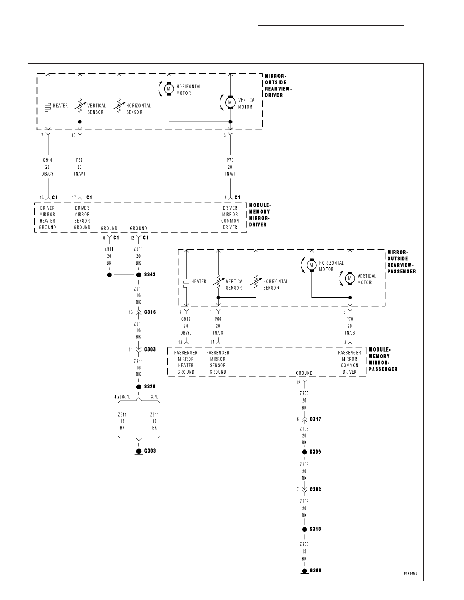
B1D1B, B1D27–MIRROR MOTOR COMMON CONTROL CIRCUIT LOW – MEMORY
MIRROR MODULE
8N - 132
POWER MIRRORS - ELECTRICAL DIAGNOSTICS
WK
|
|
|
B1D1B, B1D27–MIRROR MOTOR COMMON CONTROL CIRCUIT LOW – MEMORY 8N - 132 POWER MIRRORS - ELECTRICAL DIAGNOSTICS WK |