Jeep Grand Cherokee WK. Manual - part 475


  Index      Jeep     Jeep Grand Cherokee WK - service repair manual 2005 year


Search            


Content   ..  473  474  475  476   ..


Jeep Grand Cherokee WK. Manual - part 475


B182E–ALL DOOR LOCK CONTROL CIRCUIT HIGH– CLUSTER (CONTINUED)
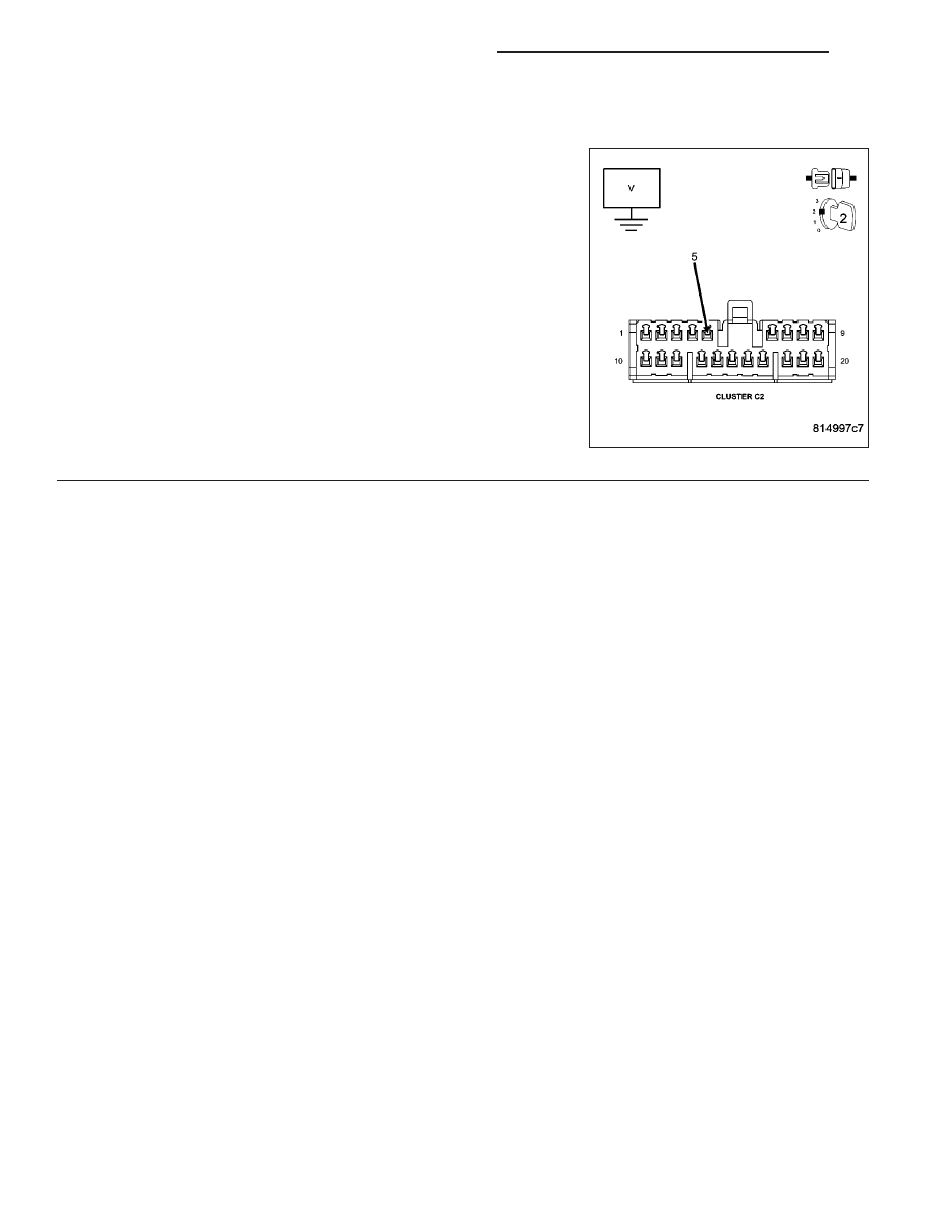
3.

(P777) DOOR LOCK RELAY CONTROL CIRCUIT SHORTED TO BATTERY

Disconnect the Junction Block C2 connector (on top of junction block).

Measure the voltage between ground and the (P777) Door Lock Relay
Control circuit in the Cluster C2 connector.

Turn the ignition on.

Is there any voltage present?

Yes

>> Repair the (P777) Door Lock Relay Control circuit for a

short to voltage.

Perform BODY VERIFICATION TEST - VER 1. (Refer to 8
- ELECTRICAL/ELECTRONIC CONTROL MODULES -
STANDARD PROCEDURE)

No

>> Replace the Junction Block in accordance with service

information.

Perform BODY VERIFICATION TEST - VER 1. (Refer to 8
- ELECTRICAL/ELECTRONIC CONTROL MODULES -
STANDARD PROCEDURE)

8N - 60

POWER LOCKS - ELECTRICAL DIAGNOSTICS

WK

B1835–DRIVER DOOR UNLOCK CONTROL CIRCUIT LOW– CLUSTER

WK

POWER LOCKS - ELECTRICAL DIAGNOSTICS

8N - 61

B1835–DRIVER DOOR UNLOCK CONTROL CIRCUIT LOW– CLUSTER (CONTINUED)

For the Power Door Lock circuit diagram (Refer to 8 - ELECTRICAL/POWER LOCKS - SCHEMATICS AND DIA-
GRAMS)

For a complete wiring diagram Refer to Section 8W.

When Monitored:
Continuously

Set Condition:
When the Cluster senses a low condition on the (P1) Driver Door Unlock Relay Control circuit for over 10
seconds, this code will set.

Possible Causes

(P1) DRIVER DOOR UNLOCK RELAY CONTROL CIRCUIT SHORT TO GROUND

JUNCTION BLOCK

INSTRUMENT CLUSTER

Theory of Operation

If the (P1) Driver Door Unlock Relay Control circuit has been shorted to ground for any length of time, the driver
door latch solenoid will probably be damaged. Check the driver door latch after the short is repaired..

Diagnostic Test

1.

TEST FOR INTERMITTENT CONDITION

With the scan tool, record and erase DTC’s

Operate the door locks several times.

Cycle the ignition from on to off.

Turn the ignition on.

With the scan tool, read DTC’s.

Does the scan tool display DRIVER DOOR UNLOCK CONTROL CIRCUIT LOW?

Yes

>> Go To 2

No

>> The conditions that caused this code to set are not present at this time. Using the wiring diagram/sche-

matic as a guide, inspect the wiring and connectors.

Perform BODY VERIFICATION TEST - VER 1. (Refer to 8 - ELECTRICAL/ELECTRONIC CONTROL
MODULES - STANDARD PROCEDURE)

8N - 62

POWER LOCKS - ELECTRICAL DIAGNOSTICS

WK

B1835–DRIVER DOOR UNLOCK CONTROL CIRCUIT LOW– CLUSTER (CONTINUED)

2.

DRIVER DOOR UNLOCK RELAY SHORTED

Turn the ignition off.

Remove the PDC fuse #13.

Disconnect the Cluster C2 connector.

Measure the resistance between ground and the (P1) Driver Door
Unlock Relay Control circuit in the Cluster C2 connector

Is the resistance below 1000.0 ohms?

No

>> Replace the Instrument Cluster in accordance with service

information.

Perform BODY VERIFICATION TEST - VER 1. (Refer to 8
- ELECTRICAL/ELECTRONIC CONTROL MODULES -
STANDARD PROCEDURE)

Yes

>> Go To 3

3.

(P1) DRIVER DOOR UNLOCK RELAY CONTROL CIRCUIT SHORT TO GROUND

Disconnect the Junction Block C2 connector (on top of junction block).

Measure the resistance between ground and the (P1) Driver Door
Unlock Relay Control circuit in the Cluster C2 connector.

Is the resistance below 1000.0 ohms?

Yes

>> Repair the (P1) Driver Door Unlock Relay Control circuit

for a short to ground.

Perform BODY VERIFICATION TEST - VER 1. (Refer to 8
- ELECTRICAL/ELECTRONIC CONTROL MODULES -
STANDARD PROCEDURE)

No

>> Replace the Junction Block in accordance with service

information.

Perform BODY VERIFICATION TEST - VER 1. (Refer to 8
- ELECTRICAL/ELECTRONIC CONTROL MODULES -
STANDARD PROCEDURE)

WK

POWER LOCKS - ELECTRICAL DIAGNOSTICS

8N - 63


Content   ..  473  474  475  476   ..