Index Jeep Jeep Grand Cherokee WK - service repair manual 2005 year
Search
Content .. 362 363 364 365 ..
Jeep Grand Cherokee WK. Manual - part 364
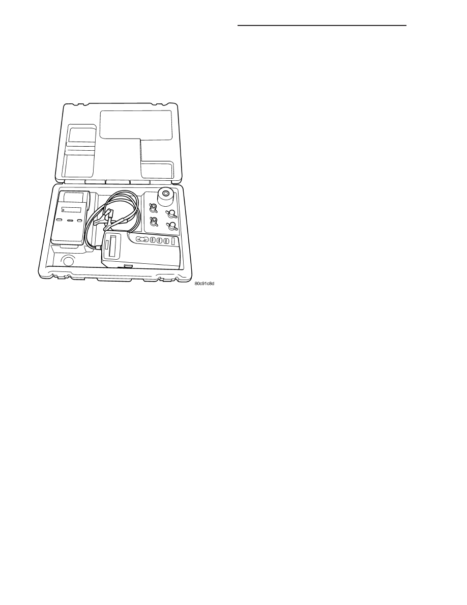
SPECIAL TOOLS
BATTERY SYSTEM SPECIAL TOOLS
8F - 8
BATTERY SYSTEM - SERVICE INFORMATION
WK