Jeep Grand Cherokee WK. Manual - part 292
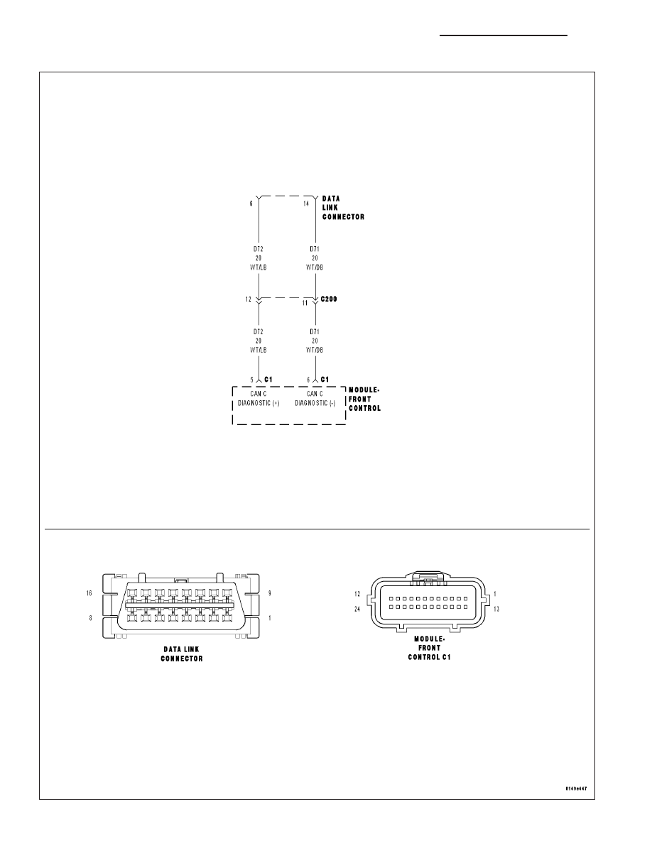
*CAN C DIAGNOSTIC (+) AND/OR CAN C DIAGNOSTIC (-) CIRCUITS HIGH
8E - 14
ELECTRONIC CONTROL MODULES - ELECTRICAL DIAGNOSTICS
WK
|
|
|
*CAN C DIAGNOSTIC (+) AND/OR CAN C DIAGNOSTIC (-) CIRCUITS HIGH 8E - 14 ELECTRONIC CONTROL MODULES - ELECTRICAL DIAGNOSTICS WK |