Jeep Grand Cherokee WK. Manual - part 1748


  Index      Jeep     Jeep Grand Cherokee WK - service repair manual 2005 year


Search            


Content   ..  1746  1747  1748  1749   ..


Jeep Grand Cherokee WK. Manual - part 1748


U0019–CAN B BUS (ATC) (CONTINUED)

3.

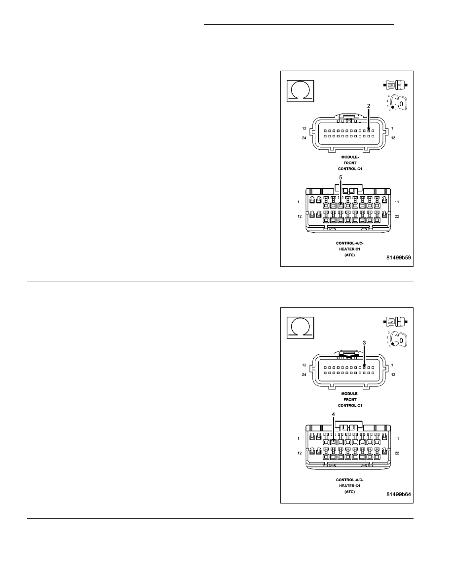
CHECK (D55) CAN B BUS (+) CIRCUIT FOR AN OPEN

Turn the ignition off.

Disconnect the negative battery cable.

Disconnect the A/C Heater Control C1 harness connector.

Disconnect the Front Control Module (FCM) C1 harness connector.

Measure the resistance of the (D55) CAN B Bus (+) circuit between
the Front Control Module C1 harness connector and the A/C Heater
Control C1 harness connector.

Is the resistance below 2.0 ohms?

Yes

>> Go To 4

No

>> Repair the (D55) CAN B Bus (+) circuit for an open.

Perform BODY VERIFICATION TEST – VER 1. (Refer to 8
- ELECTRICAL/ELECTRONIC CONTROL MODULES -
STANDARD PROCEDURE).

4.

CHECK (D54) CAN B BUS (–) CIRCUIT FOR AN OPEN

Measure the resistance of the (D54) CAN B Bus (–) circuit between
the Front Control Module C1 connector and the A/C Heater Control C1
harness connector.

Is the resistance below 2.0 ohms?

Yes

>> Replace the A/C Heater Control in accordance with the

Service Information.

Perform BODY VERIFICATION TEST – VER 1. (Refer to 8
- ELECTRICAL/ELECTRONIC CONTROL MODULES -
STANDARD PROCEDURE).

No

>> Repair the (D54) CAN B Bus (–) circuit for an open.

Perform BODY VERIFICATION TEST – VER 1. (Refer to 8
- ELECTRICAL/ELECTRONIC CONTROL MODULES -
STANDARD PROCEDURE).

24 - 340

HVAC - ELECTRICAL DIAGNOSTICS

WK

U0141–LOST COMMUNICATION WITH FRONT CONTROL MODULE (ATC)

For the Automatic Temperature Control (ATC) circuit diagram (Refer to 24 - HEATING & AIR CONDITIONING -
SCHEMATICS AND DIAGRAMS).

For a complete wiring diagram Refer to Section 8W.

When Monitored:
With the ignition on.

Set Condition:
If the A/C Heater Control looses communication with the Front Control Module (FCM).

(Refer to 8 - ELECTRICAL/ELECTRONIC CONTROL MODULES - DIAGNOSIS AND TESTING) for the diagnostic
test procedure.

U0151–LOST COMMUNICATION WITH OCCUPANT RESTRAINT CONTROLLER
(ORC) (ATC)

For the Automatic Temperature Control (ATC) circuit diagram (Refer to 24 - HEATING & AIR CONDITIONING -
SCHEMATICS AND DIAGRAMS).

For a complete wiring diagram Refer to Section 8W.

When Monitored:
With the ignition on.

Set Condition:
If the A/C Heater Control looses communication with the Occupant Restraint Controller (ORC).

(Refer to 8 - ELECTRICAL/ELECTRONIC CONTROL MODULES - DIAGNOSIS AND TESTING) for the diagnostic
test procedure.

U0154–LOST COMMUNICATION WITH OCCUPANT CLASSIFICATION MODULE
(ATC)

For the Automatic Temperature Control (ATC) circuit diagram (Refer to 24 - HEATING & AIR CONDITIONING -
SCHEMATICS AND DIAGRAMS).

For a complete wiring diagram Refer to Section 8W.

When Monitored:
With the ignition on.

Set Condition:
If the A/C Heater Control looses communication with the Occupant Classification Module (OCM).

(Refer to 8 - ELECTRICAL/ELECTRONIC CONTROL MODULES - DIAGNOSIS AND TESTING) for the diagnostic
test procedure.

U0155–LOST COMMUNICATION WITH CLUSTER/CCN (ATC)

For the Automatic Temperature Control (ATC) circuit diagram (Refer to 24 - HEATING & AIR CONDITIONING -
SCHEMATICS AND DIAGRAMS).

For a complete wiring diagram Refer to Section 8W.

When Monitored:
With the ignition on.

Set Condition:
If the A/C Heater Control looses communication with the Cluster (CCN).

(Refer to 8 - ELECTRICAL/ELECTRONIC CONTROL MODULES - DIAGNOSIS AND TESTING) for the diagnostic
test procedure.

WK

HVAC - ELECTRICAL DIAGNOSTICS

24 - 341

U0156–LOST COMMUNICATION WITH EOM (ATC)

For the Automatic Temperature Control (ATC) circuit diagram (Refer to 24 - HEATING & AIR CONDITIONING -
SCHEMATICS AND DIAGRAMS).

For a complete wiring diagram Refer to Section 8W.

When Monitored:
With the ignition on.

Set Condition:
If the A/C Heater Control looses communication with the Compass Temperature Module (EOM).

(Refer to 8 - ELECTRICAL/ELECTRONIC CONTROL MODULES - DIAGNOSIS AND TESTING) for the diagnostic
test procedure.

U0159–LOST COMMUNICATION WITH PARKING ASSIST CONTROL MODULE (ATC)

For the Automatic Temperature Control (ATC) circuit diagram (Refer to 24 - HEATING & AIR CONDITIONING -
SCHEMATICS AND DIAGRAMS).

For a complete wiring diagram Refer to Section 8W.

When Monitored:
With the ignition on.

Set Condition:
If the A/C Heater Control looses communication with the Parktronics (PTS).

(Refer to 8 - ELECTRICAL/ELECTRONIC CONTROL MODULES - DIAGNOSIS AND TESTING) for the diagnostic
test procedure.

U0167–LOST COMMUNICATION WITH INTRUSION TRANSCEIVER CONTROL
MODULE (ATC)

For the Automatic Temperature Control (ATC) circuit diagram (Refer to 24 - HEATING & AIR CONDITIONING -
SCHEMATICS AND DIAGRAMS).

For a complete wiring diagram Refer to Section 8W.

When Monitored:
With the ignition on.

Set Condition:
If the A/C Heater Control looses communication with the Intrusion Transceiver Control Module (ITM).

(Refer to 8 - ELECTRICAL/ELECTRONIC CONTROL MODULES - DIAGNOSIS AND TESTING) for the diagnostic
test procedure.

U0168–LOST COMMUNICATION WITH VEHICLE SECURITY CONTROL MODULE
(SKREEM/WCM) (ATC)

For the Automatic Temperature Control (ATC) circuit diagram (Refer to 24 - HEATING & AIR CONDITIONING -
SCHEMATICS AND DIAGRAMS).

For a complete wiring diagram Refer to Section 8W.

When Monitored:
With the ignition on.

Set Condition:
If the A/C Heater Control looses communication with the Vehicle Security Control Module (SKREEM/WCM).

(Refer to 8 - ELECTRICAL/ELECTRONIC CONTROL MODULES - DIAGNOSIS AND TESTING) for the diagnostic
test procedure.

24 - 342

HVAC - ELECTRICAL DIAGNOSTICS

WK

U0169–LOST COMMUNICATION WITH SUNROOF CONTROL MODULE (ATC)

For the Automatic Temperature Control (ATC) circuit diagram (Refer to 24 - HEATING & AIR CONDITIONING -
SCHEMATICS AND DIAGRAMS).

For a complete wiring diagram Refer to Section 8W.

When Monitored:
With the ignition on.

Set Condition:
If the A/C Heater Control looses communication with the Sunroof Control Module (SCM).

(Refer to 8 - ELECTRICAL/ELECTRONIC CONTROL MODULES - DIAGNOSIS AND TESTING) for the diagnostic
test procedure.

U0184–LOST COMMUNICATION WITH RADIO (ATC)

For the Automatic Temperature Control (ATC) circuit diagram (Refer to 24 - HEATING & AIR CONDITIONING -
SCHEMATICS AND DIAGRAMS).

For a complete wiring diagram Refer to Section 8W.

When Monitored:
With the ignition on.

Set Condition:
If the A/C Heater Control looses communication with the Radio.

(Refer to 8 - ELECTRICAL/ELECTRONIC CONTROL MODULES - DIAGNOSIS AND TESTING) for the diagnostic
test procedure.

U0186–LOST COMMUNICATION WITH AUDIO AMPLIFIER (ATC)

For the Automatic Temperature Control (ATC) circuit diagram (Refer to 24 - HEATING & AIR CONDITIONING -
SCHEMATICS AND DIAGRAMS).

For a complete wiring diagram Refer to Section 8W.

When Monitored:
With the ignition on.

Set Condition:
If the A/C Heater Control looses communication with the Amplifier (AMP).

(Refer to 8 - ELECTRICAL/ELECTRONIC CONTROL MODULES - DIAGNOSIS AND TESTING) for the diagnostic
test procedure.

U0195–LOST COMMUNICATION WITH SDARS (ATC)

For the Automatic Temperature Control (ATC) circuit diagram (Refer to 24 - HEATING & AIR CONDITIONING -
SCHEMATICS AND DIAGRAMS).

For a complete wiring diagram Refer to Section 8W.

When Monitored:
With the ignition on.

Set Condition:
If the A/C Heater Control looses communication with the Satellite Audio Receiver (SDARS).

(Refer to 8 - ELECTRICAL/ELECTRONIC CONTROL MODULES - DIAGNOSIS AND TESTING) for the diagnostic
test procedure.

WK

HVAC - ELECTRICAL DIAGNOSTICS

24 - 343


Content   ..  1746  1747  1748  1749   ..