Jeep Grand Cherokee WK. Manual - part 1496


  Index      Jeep     Jeep Grand Cherokee WK - service repair manual 2005 year


Search            


Content   ..  1494  1495  1496  1497   ..


Jeep Grand Cherokee WK. Manual - part 1496


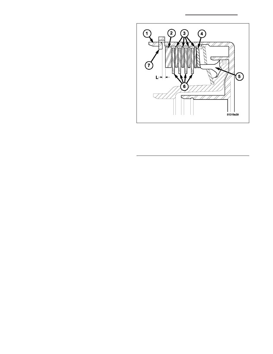
13. For transmissions using single sided friction discs,

use a feeler gauge to determine the play

9

L

9

at

three points between the snap-ring (7) and outer
multiple-disc (2).

14. During the measurement the snap-ring (7) must

contact the upper bearing surface of the groove in
the outer multiple-disc carrier.

15. The correct clutch clearance for transmissions

with single sided friction discs is 2.3-2.7 mm
(0.091-0.106 in.) for six friction disc versions, 2.4-
2.8 mm (0.095-0.110 in.) for eight disc versions,
and 2.5-2.9 mm (0.099-0.114 in.) for ten disc ver-
sions.

16. Adjust with snap-ring (7), if necessary. Snap-rings

are available in thicknesses of 2.0 mm (0.079 in.),
2.3 mm (0.091 in.), 2.6 mm (0.102 in.), 2.9 mm
(0.114 in.), 3.2 mm (0.126 in.), and 3.5 mm (0.138
in.).

1 - OUTER DISC CARRIER
2 - OUTER MULTIPLE DISC - 4.0 MM (0.158 IN.)
3 - OUTER MULTIPLE DISCS
4 - DISC SPRING
5 - PISTON
6 - INNER MULTIPLE DISCS
7 - SNAP-RING

21 - 794

AUTOMATIC TRANSMISSION - NAG1 - SERVICE INFORMATION

WK

UNIT-ELECTROHYDRAULIC

DESCRIPTION

The electrohydraulic control unit comprises the shift
plate (13) made from light alloy for the hydraulic con-
trol and an electrical control unit (12). The electrical
control unit (12) comprises of a supporting body made
of plastic, into which the electrical components (1 - 11)
are assembled. The supporting body is mounted on
the shift plate (13) and screwed to it.

Strip conductors inserted into the supporting body
make the connection between the electrical compo-
nents and a plug connector. The connection to the wir-
ing harness on the vehicle and the transmission
control module (TCM) is produced via this 13-pin plug
connector with a bayonet lock.

1 - SOLENOID CAP
2 - SOLENOID CAP
3 - BOLT - M6X32
4 - BOLT - M6X30
5 - LEAF SPRING
6 - MODULATING PRESSURE REGULATING SOLENOID VALVE
7 - SHIFT PRESSURE REGULATING SOLENOID
8 - 3-4 SHIFT SOLENOID
9 - TORQUE CONVERTER LOCK-UP SOLENOID
10 - 1-2/4-5 SHIFT SOLENOID
11 - 2-3 SHIFT SOLENOID
12 - ELECTRICHYDRAULIC CONTROL MODULE
13 - SHIFT PLATE

WK

AUTOMATIC TRANSMISSION - NAG1 - SERVICE INFORMATION

21 - 795

ELECTRICAL CONTROL UNIT

The electric valve control unit (7) consists of a plastic
shell which houses the RPM sensors (1,12), regulating
solenoid valves (3, 4), solenoid valves (5, 6, 10), the
TCC solenoid valve (11), the park/neutral contact (9),
and the transmission oil temperature sensor (8). Con-
ductor tracks integrated into the shell connect the
electric components to a plug connection (2). This
13-pin plug connection (2) establishes the connection
to the vehicle-side cable harness and to the transmis-
sion control module (TCM). With the exception of the
solenoid valves, all other electric components are
fixed to the conductor tracks.

HYDRAULIC CONTROL UNIT

Working Pressure (Line Pressure or Operating Pressure) (p-A)

The working pressure provides the pressure supply to the hydraulic control and the transmission shift elements. It is
the highest hydraulic pressure in the entire hydraulic system. The working pressure is regulated at the working pres-
sure regulating valve in relation to the load and gear. All other pressures required for the transmission control are
derived from the working pressure.

Lubrication Pressure (p-Sm)

At the working pressure regulating valve surplus oil is diverted to the lubrication pressure regulating valve, from
where it is used in regulated amounts to lubricate and cool the mechanical transmission components and the torque
converter. Furthermore, the lubrication pressure (p-Sm) is also used to limit the pressure in the torque converter.

Shift Pressure (p-S)

The shift pressure is determined by the shift pressure regulating solenoid valve and the shift pressure regulating
valve. The shift pressure:

Regulates the pressure in the activating shift element during the shift phase.

Determines together with the modulating pressure the pressure reduction at the deactivating shift element as
regulated by the overlap regulating valve.

Initializes 2nd gear in limp-home mode.

1 - N3 SPEED SENSOR
2 - PLUG CONNECTOR
3 - MODULATING PRESSURE REGULATING SOLENOID
4 - SHIFT PRESSURE REGULATING SOLENOID
5 - 1-2/4-5 SHIFT SOLENOID
6 - 3-4 SHIFT SOLENOID
7 - ELECTRICAL CONTROL UNIT
8 - TRANSMISSION TEMPERATURE SENSOR
9 - STARTER INTERLOCK CONTACT
10 - 2-3 SHIFT SOLENOID
11 - TORQUE CONVERTER LOCK-UP SOLENOID
12 - N2 SPEED SENSOR

21 - 796

AUTOMATIC TRANSMISSION - NAG1 - SERVICE INFORMATION

WK

Modulating Pressure (p-Mod)

The modulating pressure influences the size of the working pressure and determines together with the shift pressure
the pressure regulated at the overlap regulating valve. The modulating pressure is regulated at the modulating pres-
sure regulating solenoid valve, which is under regulating valve pressure. The modulating pressure is variable and
relative to the engine load.

Regulating Valve/Control Valve Pressure (p-RV)

The regulating valve pressure is regulated at the regulating valve pressure regulating valve in relation to the working
pressure (p-A) up to a maximum pressure of 8 bar (116 psi). It supplies the modulating pressure regulating solenoid
valve, the shift pressure regulating solenoid valve and the shift valve pressure regulating valve.

Shift Valve Pressure (p-SV)

The shift valve pressure (p-SV) is derived from the regulating valve pressure (p-RV), is regulated at the shift valve
pressure regulating valve and is then present at the:

1-2 and 4-5 shift solenoid valve.

3-4 shift solenoid valve.

2-3 shift solenoid valve.

Torque converter lockup solenoid valve.

3-4 and 2-3 shift pressure shift valve.

The shift valve pressure (p-SV) controls the command valves via the upshift/downshift solenoid valves.

Overlap Pressure (p-Ü)

The overlap pressure controls the shift component pressure reduction during a shift phase. The pressure in a shift
element as it disengages is controlled during the shift phase depending on engine load (modulating pressure) and
the pressure in the shift element as it engages. The adjusted pressure is inversely proportional to the transmission
capability of the shift element being engaged (controlled overlap).

Working Pressure Regulating Valve (Operating Pressure)

The working pressure regulating valve (4) is located in
the valve housing of the shift plate. It regulates the pri-
mary pressure of the hydraulic system.

1 - PRESSURE FROM K1/K2
2 - END FACE
3 - TO TORQUE CONVERTER REGULATING VALVE
4 - WORKING PRESSURE REGULATING VALVE

WK

AUTOMATIC TRANSMISSION - NAG1 - SERVICE INFORMATION

21 - 797


Content   ..  1494  1495  1496  1497   ..