Content .. 1435 1436 1437 1438 ..
Jeep Grand Cherokee WK. Manual - part 1437
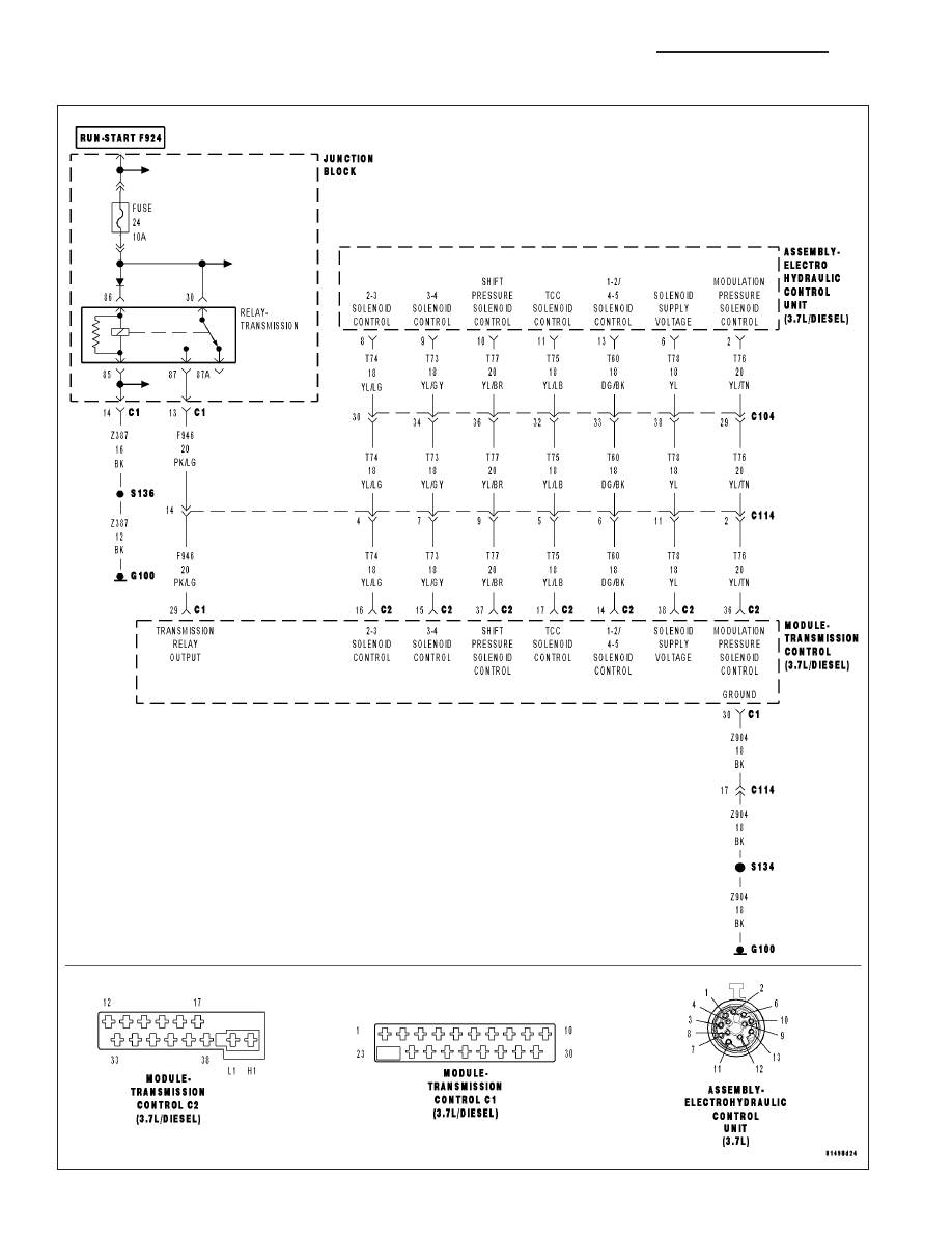
P0778-SHIFT PRESSURE SOLENOID CIRCUIT
21 - 558
AUTOMATIC TRANSMISSION NAG1 - ELECTRICAL DIAGNOSTICS
WK
|
|
|
Content .. 1435 1436 1437 1438 ..
P0778-SHIFT PRESSURE SOLENOID CIRCUIT 21 - 558 AUTOMATIC TRANSMISSION NAG1 - ELECTRICAL DIAGNOSTICS WK |