Content .. 1354 1355 1356 1357 ..
Jeep Grand Cherokee WK. Manual - part 1356
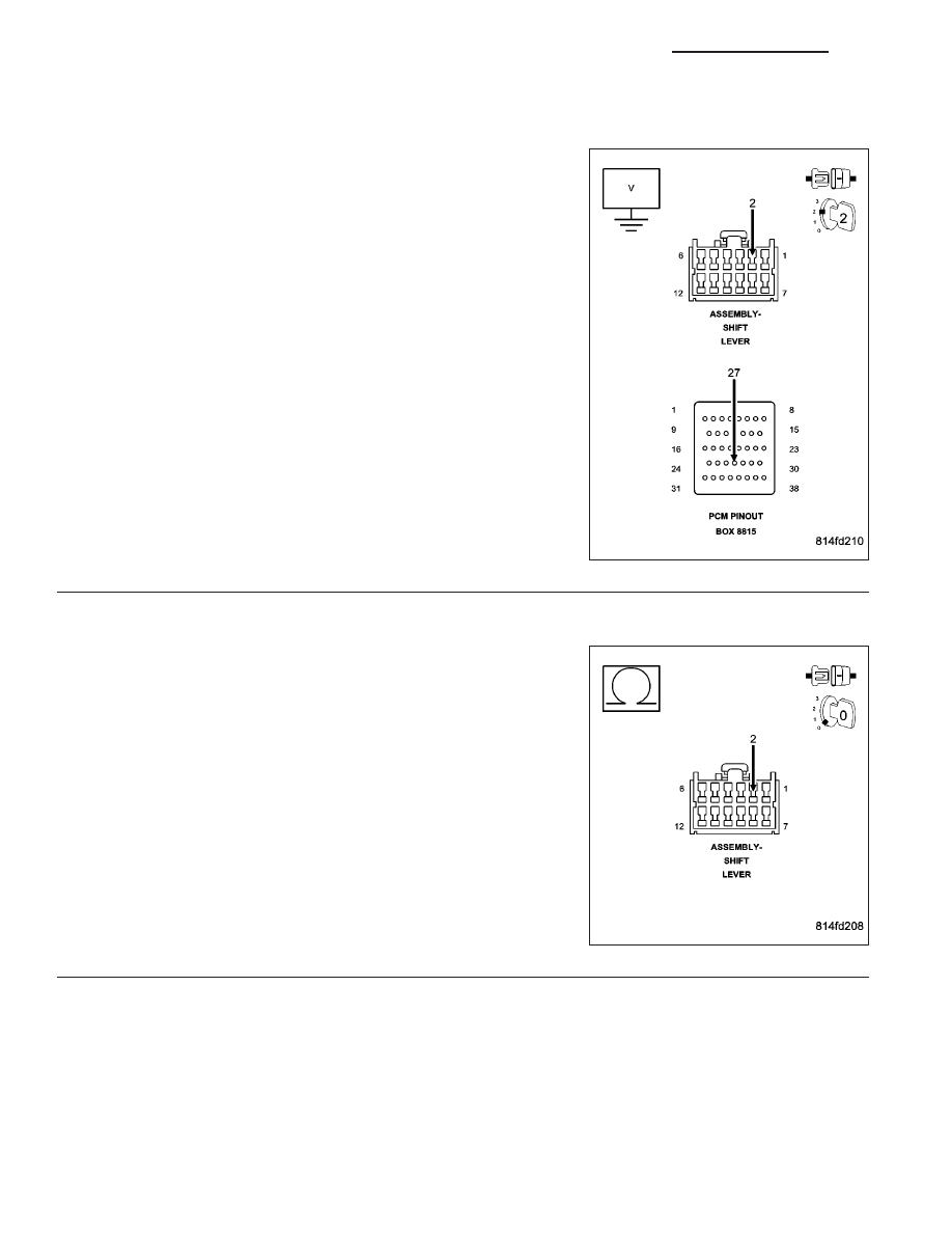
P0958-AUTOSTICK CIRCUIT HIGH (CONTINUED)
4.
CHECK THE (T5) AUTOSHIFT UP/DOWN SENSE CIRCUIT FOR A SHORT TO VOLTAGE
Ignition on, engine not running.
Measure the voltage of the (T5) AutoStick Up/Down Sense circuit.
Is the voltage above 0.5 volts?
Yes
>> Repair the (T5) AutoStick Up/Down Sense circuit for a
short to voltage.
Perform 45RFE/545RFE TRANSMISSION VERIFICATION
TEST - VER 1.
No
>> Go To 5
5.
CHECK THE (T5) AUTOSHIFT UP/DOWN SENSE CIRCUIT FOR A SHORT TO ANOTHER CIRCUIT
Turn the ignition off to the lock position.
Measure the resistance between the (T5) AutoStick Up/Down Sense
circuit and all other circuits in the Shift Lever Assembly harness con-
nector.
Is the resistance below 5.0 ohms between the (T5) AutoStick
Up/Down Sense circuit and any other circuit(s) in the Shift
Lever Assembly harness connector.
Yes
>> Repair the (T5) AutoStick Up/Down Sense circuit for a
short to another circuit(s).
Perform 45RFE/545RFE TRANSMISSION VERIFICATION
TEST - VER 1.
No
>> Go To 6
21 - 234
AUTOMATIC TRANSMISSION 545RFE - ELECTRICAL DIAGNOSTICS
WK