Content .. 1313 1314 1315 1316 ..
Jeep Grand Cherokee WK. Manual - part 1315
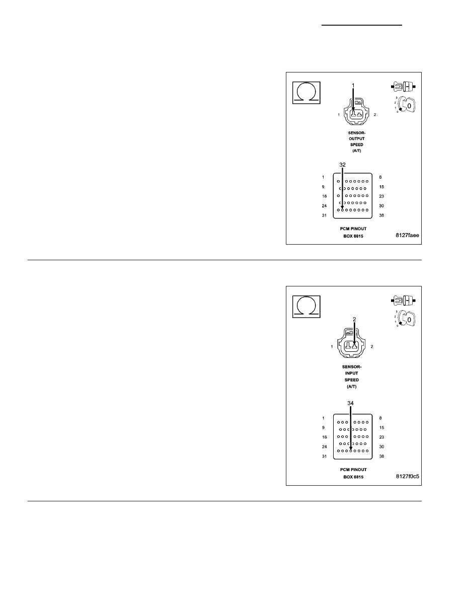
P0720-OUTPUT SPEED SENSOR CIRCUIT (CONTINUED)
3.
OUTPUT SPEED SENSOR SIGNAL CIRCUIT OPEN
Turn the ignition off to the lock position.
Disconnect the Transmission Simulator, Miller tool #8333.
Disconnect the PCM harness connectors and connect Miller special
tool #8815.
CAUTION: Do not probe the PCM harness connectors. Probing
the PCM harness connectors will damage the PCM terminals
resulting in poor terminal to pin connection. Install Miller special
tool #8815 to perform diagnosis..
Measure the resistance of the Output Speed Sensor Signal circuit from
the Output Speed Sensor harness connector to the appropriate termi-
nal of special tool #8815.
Is the resistance above 5.0 ohms?
Yes
>> Repair the Output Speed Sensor Signal circuit for an
open.
Perform 45RFE/545RFE TRANSMISSION VERIFICATION
TEST - VER 1.
No
>> Go To 4
4.
SPEED SENSOR GROUND CIRCUIT OPEN
Measure the resistance of the Speed Sensor Ground circuit from the
Output Speed Sensor harness connector to the appropriate terminal in
the special tool #8815.
Is the resistance above 5.0 ohms?
Yes
>> Repair the Speed Sensor Ground circuit for an open.
Perform 45RFE/545RFE TRANSMISSION VERIFICATION
TEST - VER 1.
No
>> Go To 5
21 - 70
AUTOMATIC TRANSMISSION 545RFE - ELECTRICAL DIAGNOSTICS
WK