Jeep Grand Cherokee WK. Manual - part 1231


  Index      Jeep     Jeep Grand Cherokee WK - service repair manual 2005 year


Search            


Content   ..  1229  1230  1231  1232   ..


Jeep Grand Cherokee WK. Manual - part 1231


INSTALLATION

1. Throughly clean all gasket resdue from the engine

block.

2. Use extream care and clean all gasket resdue from

the retainer.

3. Position the gasket onto the retainer.

4. Position the retainer onto the engine block.

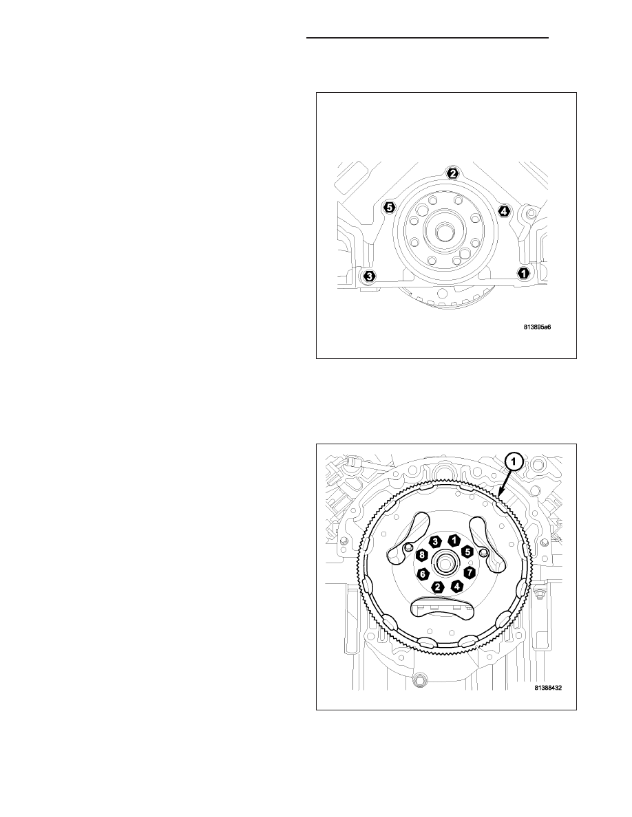
5. Install the retainer mounting bolts. Tighten the bolts

to 15 N·m (132 in. lbs.) using the procedure shown.

6. Install the oil pan (Refer to 9 - ENGINE/LUBRICA-

TION/OIL PAN - INSTALLATION).

7. Install the flexplate (Refer to 9 - ENGINE/ENGINE

BLOCK/FLEX PLATE - INSTALLATION).

8. Install the transmission (Refer to 21 - TRANSMIS-

SION/TRANSAXLE/AUTOMATIC

-

NAG1

-

INSTALLATION).

9. Check and verify engine oil level.

10. Start engine and check for leaks.

FLEX PLATE

REMOVAL

1. Remove the transmission. (Refer to 21 - TRANS-

MISSION/TRANSAXLE/AUTOMATIC

-

NAG1

-

REMOVAL).

2. Remove the bolts and flexplate (1).

9 - 1520

ENGINE - 5.7L SERVICE INFORMATION

WK

INSTALLATION

1. Position the flexplate or flywheel onto the crank-

shaft and install the bolts hand tight.

2. For automatic transmissions: Tighten the flex-

plate retaining bolts to 95 N·m (70 ft. lbs.).

3. Install the transmission. (Refer to 21 - TRANSMISSION/TRANSAXLE/AUTOMATIC - NAG1 - INSTALLATION).

TAPPETS-HYDRAULIC ROLLER

DIAGNOSIS AND TESTING - HYDRAULIC TAPPETS

Before disassembling any part of the engine to correct tappet noise, check the oil pressure. If vehicle has no oil
pressure gauge, install a reliable gauge at the pressure sending-unit. The pressure should be between 207-552 kPa
(30-70 psi) at 3,000 RPM.

Check the oil level after the engine reaches normal operating temperature. Allow 5 minutes to stabilize oil level,
check dipstick. The oil level in the pan should never be above the FULL mark or below the ADD OIL mark on
dipstick. Either of these two conditions could be responsible for noisy tappets.

OIL LEVEL

HIGH

If oil level is above the FULL mark, it is possible for the connecting rods to dip into the oil. With the engine running,
this condition could create foam in the oil pan. Foam in oil pan would be fed to the hydraulic tappets by the oil pump
causing them to lose length and allow valves to seat noisily.

LOW

Low oil level may allow oil pump to take in air. When air is fed to the tappets, they lose length, which allows valves
to seat noisily. Any leaks on intake side of oil pump through which air can be drawn will create the same tappet
action. Check the lubrication system from the intake strainer to the pump cover, including the relief valve retainer
cap. When tappet noise is due to aeration, it may be intermittent or constant, and usually more than one tappet will
be noisy. When oil level and leaks have been corrected, operate the engine at fast idle. Run engine for a sufficient
time to allow all of the air inside the tappets to be bled out.

TAPPET NOISE DIAGNOSIS

1. To determine source of tappet noise, crank over engine with cylinder head covers removed.

WK

ENGINE - 5.7L SERVICE INFORMATION

9 - 1521

2. Feel each valve spring or rocker arm to detect noisy tappet. The noisy tappet will cause the affected spring

and/or rocker arm to vibrate or feel rough in operation.

NOTE: Worn valve guides or cocked springs are sometimes mistaken for noisy tappets. If such is the case,
noise may be dampened by applying side thrust on the valve spring. If noise is not appreciably reduced, it
can be assumed the noise is in the tappet. Inspect the rocker arm push rod sockets and push rod ends for
wear.

3. Valve tappet noise ranges from light noise to a heavy click. A light noise is usually caused by excessive leak-

down around the unit plunger, or by the plunger partially sticking in the tappet body cylinder. The tappet should
be replaced. A heavy click is caused by a tappet check valve not seating, or by foreign particles wedged between
the plunger and the tappet body. This will cause the plunger to stick in the down position. This heavy click will be
accompanied by excessive clearance between the valve stem and rocker arm as valve closes. In either case,
tappet assembly should be removed for inspection and cleaning.

4. The valve train generates a noise very much like a light tappet noise during normal operation. Care must be

taken to ensure that tappets are making the noise. If more than one tappet seems to be noisy, it’s probably not
the tappets.

REMOVAL

1. Disconnect the negative cable from the battery.

2. Remove the air cleaner (Refer to 9 - ENGINE/AIR INTAKE SYSTEM - REMOVAL).

3. Remove intake manifold (Refer to 9 - ENGINE/MANIFOLDS/INTAKE MANIFOLD - REMOVAL).

4. Remove cylinder head cover (Refer to 9 - ENGINE/CYLINDER HEAD/CYLINDER HEAD COVER(S) -

REMOVAL).

5. Remove rocker arm assembly and push rods (Refer to 9 - ENGINE/CYLINDER HEAD/ROCKER ARM /

ADJUSTER ASSY - REMOVAL). Identify push rods to ensure installation in original location.

6. Remove the cylinder head (Refer to 9 - ENGINE/CYLINDER HEAD - REMOVAL).

7. Remove bolt from tappet guide holder.

8. Remove tappet guide holder.

9 - 1522

ENGINE - 5.7L SERVICE INFORMATION

WK

9. Pull tappet out of bore with a twisting motion. If all tappets are to be removed and reused, identify tappets

to ensure installation in original location.

10. Check camshaft lobes for abnormal wear.

INSTALLATION

1. Lubricate tappets.

2. Install tappets in their original positions.

CAUTION: The 5.7L LX engine uses both standard roller tappets and deactivating roller tappets, for use with
the Multi Displacement System. The deactivating roller tappets must be used in cylinders 1,4,6,7. The deac-
tivating tappets can be identified by the two holes in the side of the tappet body, for the latching pins.

3. Install tappet guide yoke. Install the tappet guide yoke bolt and tighten to 12 N·m (106 in. lbs.) torque.

4. Install cylinder head (Refer to 9 - ENGINE/CYLINDER HEAD - INSTALLATION).

5. Install pushrods and rocker arm assembly (Refer to 9 - ENGINE/CYLINDER HEAD/ROCKER ARM / ADJUSTER

ASSY - INSTALLATION).

6. Install cylinder head cover (Refer to 9 - ENGINE/CYLINDER HEAD/CYLINDER HEAD COVER(S) - INSTALLA-

TION).

7. Install intake manifold (Refer to 9 - ENGINE/MANIFOLDS/INTAKE MANIFOLD - INSTALLATION).

8. Install the air cleaner (Refer to 9 - ENGINE/AIR INTAKE SYSTEM - INSTALLATION).

9. Connect the negative cable to the battery.

CAUTION: To prevent damage to valve mechanism, engine must not be run above fast idle until all hydrau-
lic tappets have filled with oil and have become quiet.

10. Road test vehicle and check for leaks.

WK

ENGINE - 5.7L SERVICE INFORMATION

9 - 1523


Content   ..  1229  1230  1231  1232   ..