Jeep Grand Cherokee WK. Manual - part 1193


  Index      Jeep     Jeep Grand Cherokee WK - service repair manual 2005 year


Search            


Content   ..  1191  1192  1193  1194   ..


Jeep Grand Cherokee WK. Manual - part 1193


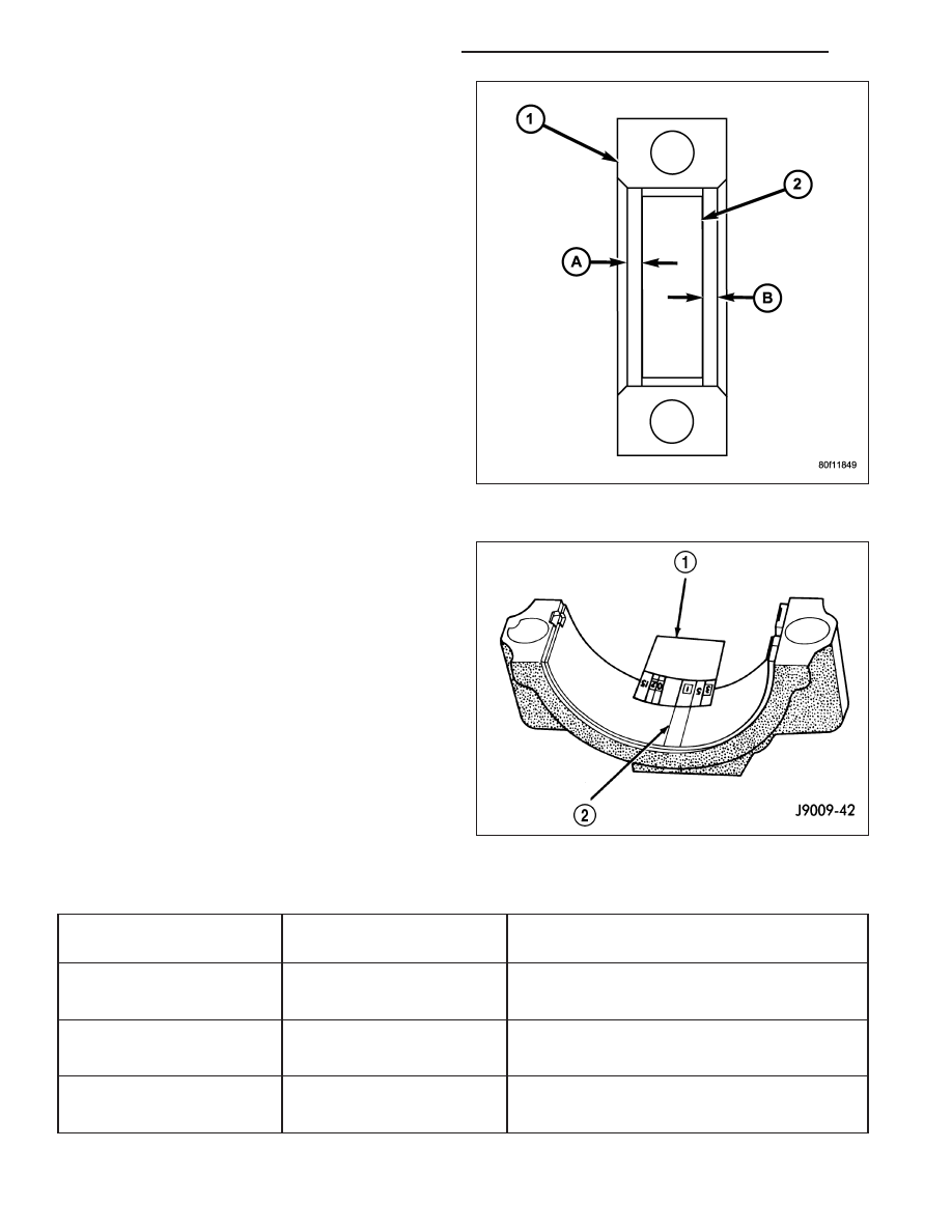
4. Install the lower bearing insert in the bearing cap

Center bearing insert (2) in connecting rod (1)..
The lower insert must be dry. Place strip of Plasti-
gage across full width of the lower insert at the
center of bearing cap. Plastigage must not crumble
in use. If brittle, obtain fresh stock.

5. Install bearing cap and connecting rod on the jour-

nal and tighten bolts to 27 N·m (20 ft. lbs.) plus a
90° turn. DO NOT rotate crankshaft. Plastigage will
smear, resulting in inaccurate indication.

6. Remove the bearing cap and determine amount of

bearing-to-journal

clearance

by

measuring

the

width of compressed Plastigage (2). Refer to
Engine Specifications for the proper clearance.
Plastigage should indicate the same clearance
across the entire width of the insert. If the
clearance varies, it may be caused by either a
tapered journal, bent connecting rod or foreign
material trapped between the insert and cap or
rod.

7. If the correct clearance is indicated, replacement of

the bearing inserts is not necessary. Remove the
Plastigage (2) from crankshaft journal and bearing
insert. Proceed with installation.

Bearing Mark

SIZE

USED WITH

JOURNAL SIZE

.025 US

.025 mm

50.983-50.967 mm

(.001 in.)

(2.0073-2.0066 in.)

Std.

STANDARD

50.992-51.008 mm

(2.0076-2.0082 in.)

.250 US

.250 mm

50.758-50.742 mm

(.010 in.)

(1.9984-1.9978 in.)

9 - 1368

ENGINE - 4.7L SERVICE INFORMATION

WK

8. If bearing-to-journal clearance exceeds the specification, determine which service bearing set to use, using the

following bearing sizes:

CAUTION: Connecting Rod Bolts are Torque to
Yield Bolts and Must Not Be Reused. Always
replace the Rod Bolts whenever they are loosened
or removed.

9. Repeat the Plastigage measurement to verify your

bearing selection prior to final assembly.

10. Once you have selected the proper insert, install

the insert and cap. Tighten the connecting rod
bolts to 27 N·m (20 ft. lbs.) plus a 90° turn.

Slide snug-fitting feeler gauge between the connecting
rod and crankshaft journal flange. Refer to Engine
Specifications for the proper clearance. Replace the
connecting rod if the side clearance is not within
specification.

CRANKSHAFT

DESCRIPTION

The 4.7L crankshaft is constructed of nodular cast iron. The crankshaft is a cross shaped four throw design with
eight counterweights for balancing purposes. The crankshaft is supported by five select fit main bearings with the
number three serving as the thrust washer location. The main journals of the crankshaft are cross drilled to improve
rod bearing lubrication. The number eight counterweight has provisions for crankshaft position sensor target wheel
mounting. The select fit main bearing markings are located on the rear side of the target wheel. The crankshaft oil
seals are one piece design. The front oil seal is retained in the timing chain cover, and the rear seal is pressed in
to a bore formed by the cylinder block and the bedplate assembly.

STANDARD PROCEDURE

MEASURING CRANKSHAFT END PLAY

1.

Mount a dial indicator to front of engine with the locating probe on nose of crankshaft.

2.

Move crankshaft all the way to the rear of its travel.

3.

Zero the dial indicator.

4.

Move crankshaft all the way to the front and read the dial indicator. (Refer to 9 - ENGINE - SPECIFICATIONS)

for end play specification.

WK

ENGINE - 4.7L SERVICE INFORMATION

9 - 1369

REMOVAL

NOTE: To remove the crankshaft from the engine,
the engine must be removed from the vehicle.

1. Remove the engine. (Refer to 9 - ENGINE -

REMOVAL).

2. Remove the engine oil pump. (Refer to 9 -

ENGINE/LUBRICATION/OIL PUMP - REMOVAL).

CAUTION: DO NOT pry on the oil pan gasket when
removing the oil pan, The oil pan gasket is
mounted to the cylinder block in three locations
and will remain attached to block when removing
oil pan. Gasket can not be removed with oil pan.

3. Remove oil pan. (Refer to 9 - ENGINE/LUBRICATION/OIL PAN - REMOVAL).

4. Remove the oil pump pickup tube and oil pan gasket /windage tray.

5. Remove the bedplate mounting bolts. Note the location of the three stud bolts for installation.

6. Remove the connecting rods from the crankshaft.

CAUTION: The bedplate to cylinder block mating
surface is a critical sealing surface. Do not pry on
or damage this surface in anyway.

NOTE: The bedplate contains the lower main bear-
ing halves. Use care when handling bedplate as
not to drop or damage bearing halves. Installing
main bearing halves in the wrong position will
cause sever damage to the crankshaft.

NOTE: The bedplate has pry points cast into it.
Use these points only. The pry points are on both
the left and right sides, only the left side is shown.

7. Carefully pry on the pry points to loosen the bed-

plate then remove the bedplate.

CAUTION: When removing the crankshaft, use
care not to damage bearing surfaces on the crankshaft.

8. Remove the crankshaft.

9. Remove the crankshaft target wheel.

INSPECTION

NOTE: Thoroughly inspect the connecting rod bearing bores and main bearing bores for scoring, blueing or
severe scratches. Further disassembly may be required.

If connecting rod bearing bores show damage, the cylinder heads must be removed to service the piston and rod
assemblies. If the bedplate or the cylinder block main bearing bores show damage the engine must be replaced.

1. If required, remove the main bearing halves from the cylinder block and bedplate.

2. Thoroughly clean the bedplate to cylinder block sealing surfaces and main bearing bores. Remove all oil and

sealant residue.

9 - 1370

ENGINE - 4.7L SERVICE INFORMATION

WK

3. Inspect the bedplate main bearing bores for cracks, scoring or severe blueing. If either condition exists the

engine must be replaced.

4. Inspect the crankshaft thrust washers for scoring, scratches, wear or blueing. If either condition exist replace the

thrust washer.

5. Inspect the oil pan gasket/windage tray for splits, tears or cracks in the gasket sealing surfaces. Replace gasket

as necessary.

INSTALLATION

CAUTION: Main bearings are select fit. (Refer to 9
-

ENGINE/ENGINE

BLOCK/CRANKSHAFT

MAIN

BEARINGS - STANDARD PROCEDURE) for proper
bearing selections.

1. Lubricate upper main bearing halves with clean

engine oil.

CAUTION: When installing crankshaft, use care
not to damage bearing surfaces on the crankshaft.

NOTE: Apply sealant to the target wheel retaining
screws prior to installation.

2. Install the crankshaft target wheel. Torque the

mounting screws to 15 N·m (12 ft. lbs.).

3. Position crankshaft in cylinder block.

4. Install the thrust washers (1).

WK

ENGINE - 4.7L SERVICE INFORMATION

9 - 1371


Content   ..  1191  1192  1193  1194   ..