Jeep Grand Cherokee WK. Manual - part 1190


  Index      Jeep     Jeep Grand Cherokee WK - service repair manual 2005 year


Search            


Content   ..  1188  1189  1190  1191   ..


Jeep Grand Cherokee WK. Manual - part 1190


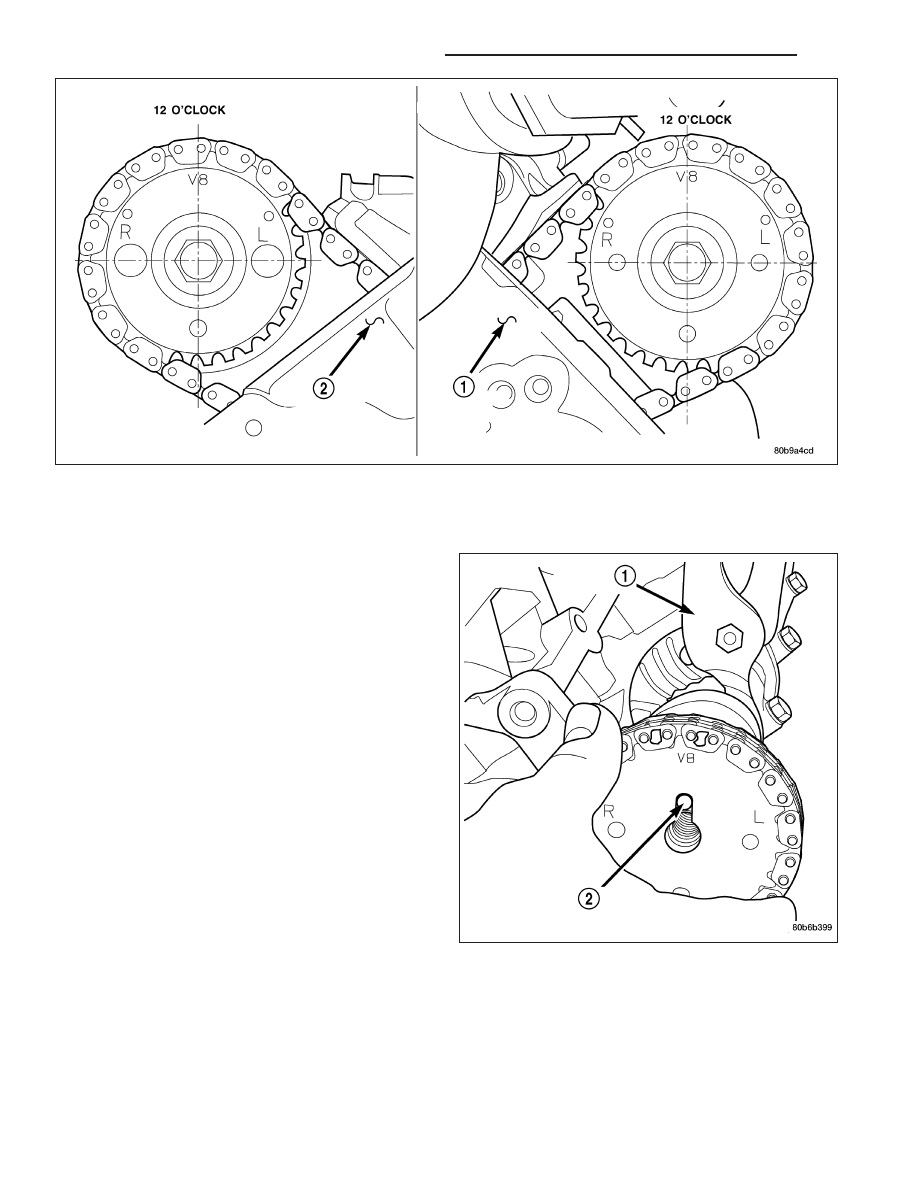
6. Position the camshaft drive gear into the timing chain aligning the V8 mark (2) between the two marked chain

links (Two links marked during removal).

NOTE: When gripping the camshaft, place the pli-
ers on the tube portion of the camshaft only. Do
not grip the lobes or the sprocket areas.

7. Using the adjustable pliers (1), rotate the camshaft

until the camshaft sprocket dowel (2) is aligned
with the slot in the camshaft sprocket (2). Install
the sprocket onto the camshaft.

CAUTION:

Remove

excess

oil

from

camshaft

sprocket bolt. Failure to do so can cause bolt
over-torque resulting in bolt failure.

8. Remove excess oil from camshaft sprocket bolt,

then install the camshaft sprocket retaining bolt and
hand tighten.

9 - 1356

ENGINE - 4.7L SERVICE INFORMATION

WK

9. Remove timing chain wedge special tool 8350 (3).

10. Using Special Tool 6958 spanner wrench with

adapter pins 8346 (2), torque the camshaft
sprocket retaining bolt (4) to 122 N·m (90 ft. lbs.).

WK

ENGINE - 4.7L SERVICE INFORMATION

9 - 1357

11. Install the camshaft position sensor.

12. Install the cylinder head cover (1) (Refer to 9 -

ENGINE/CYLINDER

HEAD/CYLINDER

HEAD

COVER(S) - INSTALLATION).

COVER - CYLINDER HEAD - RIGHT

DESCRIPTION

The cylinder head covers are made of injection molded thermo-set plastic, and are not interchangeable from side-
to-side. It is imperative that nothing rest on the cylinder head covers. Prolonged contact with other items may wear
a hole in the cylinder head cover.

REMOVAL - RIGHT SIDE

1. Disconnect battery negative cable.

2. Disconnect battery positive cable.

3. Remove the battery tray.

4. Drain cooling system (Refer to 7 - COOLING - STANDARD PROCEDURE).

5. Remove accessory drive belt (Refer to 7 - COOLING/ACCESSORY DRIVE/DRIVE BELTS - REMOVAL).

6. Remove air conditioning compressor retaining bolts and move compressor to the left.

7. Remove heater hoses.

8. Disconnect injector and ignition coil connectors.

9. Disconnect and remove positive crankcase ventilation (PCV) hose.

10. Remove oil fill tube.

11. Un-clip injector and ignition coil harness and move away from cylinder head cover.

12. Remove right rear breather tube and filter assembly.

9 - 1358

ENGINE - 4.7L SERVICE INFORMATION

WK

13. Remove cylinder head cover retaining bolts.

14. Remove cylinder head cover.

NOTE: The gasket may be used again, provided no cuts, tears, or deformation has occurred.

CLEANING

Clean cylinder head cover gasket surface.

Clean head rail, if necessary.

INSTALLATION - RIGHT SIDE

CAUTION: Do not use harsh cleaners to clean the
cylinder head covers. Severe damage to covers
may occur.

1. Clean cylinder head cover and both sealing sur-

faces. Inspect and replace gasket as necessary.

2. Install cylinder head cover and hand start all fas-

teners (1). Verify that all double ended studs are in
the correct location shown in.

3. Tighten cylinder head cover bolts and double

ended studs to 12 N·m (105 in. lbs).

4. Install right rear breather tube and filter assembly.

5. Connect injector, ignition coil electrical connectors and harness retaining clips.

6. Install the oil fill tube.

7. Install PCV hose.

8. Install heater hoses.

9. Install air conditioning compressor retaining bolts.

10. Install accessory drive belt (Refer to 7 - COOLING/ACCESSORY DRIVE/DRIVE BELTS - INSTALLATION).

11. Fill Cooling system (Refer to 7 - COOLING - STANDARD PROCEDURE).

12. Install air cleaner assembly, resonator assembly and air inlet hose.

13. Connect battery negative cable.

VALVES & SEATS - INTAKE/EXHAUST

DESCRIPTION

The valves are made of heat resistant steel and have chrome plated stems to prevent scuffing. Each valve is actu-
ated by a roller rocker arm which pivots on a stationary lash adjuster. All valves use three bead lock keepers to
retain the springs and promote valve rotation.

WK

ENGINE - 4.7L SERVICE INFORMATION

9 - 1359


Content   ..  1188  1189  1190  1191   ..