Content .. 1148 1149 1150 1151 ..
Jeep Grand Cherokee WK. Manual - part 1150
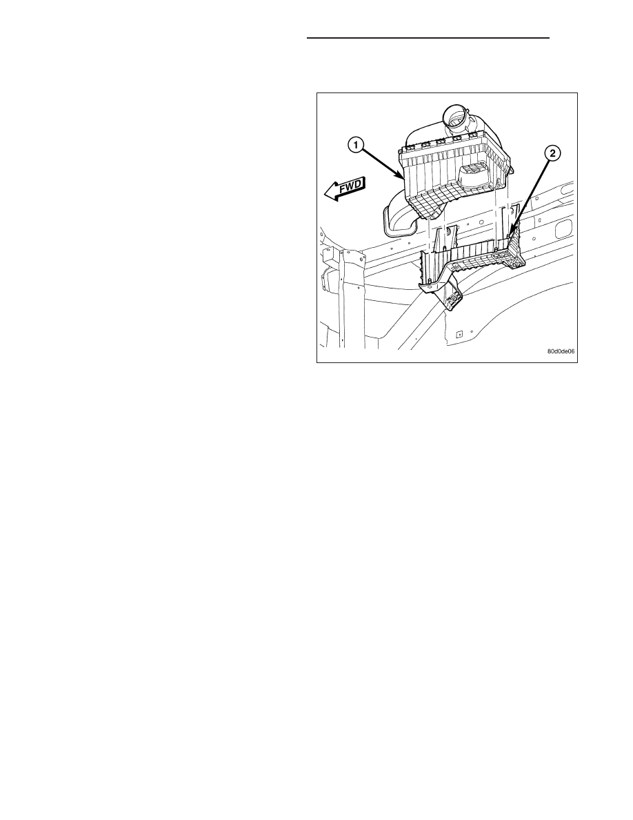
INSTALLATION
1. Install filter element into housing (1).
2. Position housing cover into housing locating tabs.
3. Pry up 4 spring clips and lock cover to housing.
4. Install air duct to air cleaner cover and tighten hose
clamp to 3 N·m (30 in. lbs.) torque.
5. If any other hose clamps were removed from air
intake system, tighten them to 3.4 N·m (30 in. lbs.)
torque.
6. If any bolts were removed from air resonator hous-
ing or air intake tubing, tighten them to 4.5 N·m (40
in. lbs.) torque.
CYLINDER HEAD
DESCRIPTION
CYLINDER HEAD
The cylinder heads are made of an aluminum alloy. The cylinder head features two valves per cylinder with pressed
in powdered metal valve guides. The cylinder heads also provide enclosures for the timing chain drain, necessitating
unique left and right cylinder heads.
VALVE GUIDE SEALS
The valve guide seals are made of rubber and incorporate an integral steel valve spring seat. The integral garter
spring maintains consistent lubrication control to the valve stems.
DIAGNOSIS AND TESTING
CYLINDER HEAD GASKET
A cylinder head gasket leak can be located between adjacent cylinders or between a cylinder and the adjacent
water jacket.
Possible indications of the cylinder head gasket leaking between adjacent cylinders are:
•
Loss of engine power
•
Engine misfiring
•
Poor fuel economy
Possible indications of the cylinder head gasket leaking between a cylinder and an adjacent water jacket are:
•
Engine overheating
•
Loss of coolant
•
Excessive steam (white smoke) emitting from exhaust
•
Coolant foaming
9 - 1196
ENGINE - 3.7L SERVICE INFORMATION
WK