Jeep Grand Cherokee WK. Manual - part 1101


  Index      Jeep     Jeep Grand Cherokee WK - service repair manual 2005 year


Search            


Content   ..  1099  1100  1101  1102   ..


Jeep Grand Cherokee WK. Manual - part 1101


P2175-LOW AIRFLOW/RESTRICTION DETECTED (SLOW ACCUMULATION) (CONTINUED)

8.

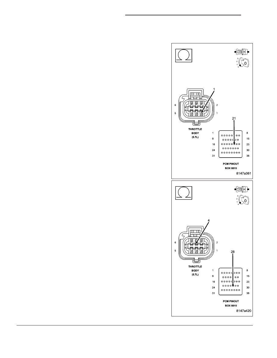
RESISTANCE IN THE TP SENSOR SIGNAL CIRCUIT

Turn the ignition off.

Disconnect the C2 PCM harness connector.

Measure the resistance of the (K22) and (K122) TP Signal circuits
from the Throttle Body harness connector to the appropriate terminals
of special tool #8815.

Is the resistance below 5.0 ohms for each circuit?

Yes

>> Go To 9

No

>> Repair the excessive resistance in the (K22) or (K122) TP

Sensor Signal circuit.

Perform the POWERTRAIN VERIFICATION TEST. (Refer
to 9 - ENGINE - STANDARD PROCEDURE)

9 - 1000

ENGINE ELECTRICAL DIAGNOSTICS

WK

P2175-LOW AIRFLOW/RESTRICTION DETECTED (SLOW ACCUMULATION) (CONTINUED)

9.

TP SENSOR SIGNAL CIRCUIT SHORTED TO GROUND

Measure the resistance between ground and the (K22) and (K122) TP
Signal circuits at the appropriate terminals of special tool #8815.

Is the resistance above 100k ohms for each circuit?

Yes

>> Go To 10

No

>> Repair the short to ground in the (K22) or (K122) TP Sen-

sor Signal circuit.

Perform the POWERTRAIN VERIFICATION TEST. (Refer
to 9 - ENGINE - STANDARD PROCEDURE)

WK

ENGINE ELECTRICAL DIAGNOSTICS

9 - 1001

P2175-LOW AIRFLOW/RESTRICTION DETECTED (SLOW ACCUMULATION) (CONTINUED)

10.

RESISTANCE IN THE (K922) SENSOR RETURN CIRCUIT

Measure the resistance of the (K922) Sensor Return circuit from the
Throttle Body harness connector to the appropriate terminal of special
tool #8815.

Is the resistance below 5.0 ohms?

Yes

>> Go To 17

No

>> Repair the excessive resistance in the (K922) Sensor

Return circuit.

Perform the POWERTRAIN VERIFICATION TEST. (Refer
to 9 - ENGINE - STANDARD PROCEDURE)

11.

RESISTANCE IN THE (F856) 5-VOLT SUPPLY CIRCUIT

Turn the ignition off.

Disconnect the MAP Sensor harness connector.

Disconnect the C1 PCM harness connector.

CAUTION: Do not probe the PCM harness connectors. Probing
the PCM harness connectors will damage the PCM terminals
resulting in poor terminal to pin connection. Install Miller Special
Tool #8815 to perform diagnosis.
Measure the resistance of the (F856) 5-volt Supply circuit from the
MAP Sensor harness connector to the appropriate terminal of special
tool #8815.

Is the resistance below 5.0 ohms?

Yes

>> Go To 12

No

>> Repair the excessive resistance in the (F856) 5-volt Sup-

ply circuit.

Perform the POWERTRAIN VERIFICATION TEST. (Refer
to 9 - ENGINE - STANDARD PROCEDURE)

9 - 1002

ENGINE ELECTRICAL DIAGNOSTICS

WK

P2175-LOW AIRFLOW/RESTRICTION DETECTED (SLOW ACCUMULATION) (CONTINUED)

12.

(F856) 5-VOLT SUPPLY CIRCUIT SHORTED TO GROUND

Measure the resistance between ground and the (F856) 5-volt Supply
circuit in the MAP Sensor harness connector.

Is the resistance above 100k ohms?

Yes

>> Go To 13

No

>> Repair the short to ground in the (F856) 5-volt Supply cir-

cuit.

Perform the POWERTRAIN VERIFICATION TEST. (Refer
to 9 - ENGINE - STANDARD PROCEDURE)

13.

MAP SENSOR

Connect the C1 PCM harness connector.

Ignition on, engine not running.

With a scan tool, monitor the MAP Sensor voltage.

Connect a jumper wire between the (K1) MAP Signal circuit and the
(K900) Sensor ground circuit.

Cycle the ignition switch from off to on.

With a scan tool, monitor the MAP Sensor voltage.

Does the scan tool display MAP voltage from approximately 4.9
volts to below 0.5 volt with the jumper wire installed?

Yes

>> Replace the MAP Sensor.

Perform the POWERTRAIN VERIFICATION TEST. (Refer
to 9 - ENGINE - STANDARD PROCEDURE)

No

>> Go To 14

NOTE: Remove the jumper wire before continuing.

WK

ENGINE ELECTRICAL DIAGNOSTICS

9 - 1003


Content   ..  1099  1100  1101  1102   ..