Jeep Grand Cherokee WK. Manual - part 1096


  Index      Jeep     Jeep Grand Cherokee WK - service repair manual 2005 year


Search            


Content   ..  1094  1095  1096  1097   ..


Jeep Grand Cherokee WK. Manual - part 1096


P2173-HIGH AIRFLOW/VACUUM LEAK DETECTED (SLOW ACCUMULATION) (CONTINUED)

10.

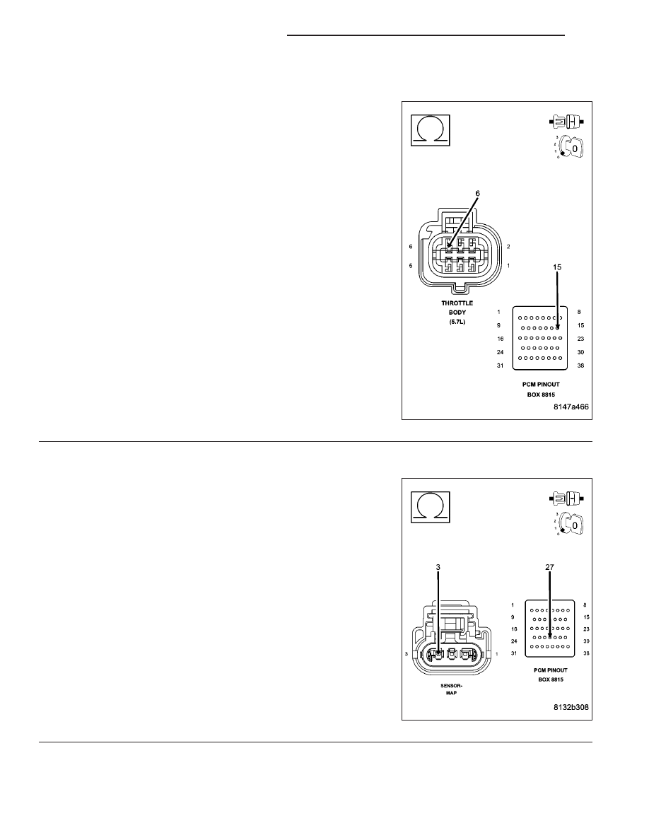
RESISTANCE IN THE (K922) SENSOR RETURN CIRCUIT

Measure the resistance of the (K922) Sensor Return circuit from the
Throttle Body harness connector to the appropriate terminal of special
tool #8815.

Is the resistance below 5.0 ohms?

Yes

>> Go To 17

No

>> Repair the excessive resistance in the (K922) Sensor

Return circuit.

Perform the POWERTRAIN VERIFICATION TEST. (Refer
to 9 - ENGINE - STANDARD PROCEDURE)

11.

RESISTANCE IN THE (F856) 5-VOLT SUPPLY CIRCUIT

Turn the ignition off.

Disconnect the MAP Sensor harness connector.

Disconnect the C1 PCM harness connector.

CAUTION: Do not probe the PCM harness connectors. Probing
the PCM harness connectors will damage the PCM terminals
resulting in poor terminal to pin connection. Install Miller Special
Tool #8815 to perform diagnosis.
Measure the resistance of the (F856) 5-volt Supply circuit from the
MAP Sensor harness connector to the appropriate terminal of special
tool #8815.

Is the resistance below 5.0 ohms?

Yes

>> Go To 12

No

>> Repair the excessive resistance in the (F856) 5-volt Sup-

ply circuit.

Perform the POWERTRAIN VERIFICATION TEST. (Refer
to 9 - ENGINE - STANDARD PROCEDURE)

9 - 980

ENGINE ELECTRICAL DIAGNOSTICS

WK

P2173-HIGH AIRFLOW/VACUUM LEAK DETECTED (SLOW ACCUMULATION) (CONTINUED)

12.

(F856) 5-VOLT SUPPLY CIRCUIT SHORTED TO GROUND

Measure the resistance between ground and the (F856) 5-volt Supply
circuit in the MAP Sensor harness connector.

Is the resistance above 100k ohms?

Yes

>> Go To 13

No

>> Repair the short to ground in the (F856) 5-volt Supply cir-

cuit.

Perform the POWERTRAIN VERIFICATION TEST. (Refer
to 9 - ENGINE - STANDARD PROCEDURE)

13.

MAP SENSOR

Connect the C1 PCM harness connector.

Ignition on, engine not running.

With a scan tool, monitor the MAP Sensor voltage.

Connect a jumper wire between the (K1) MAP Signal circuit and the
(K900) Sensor ground circuit in the MAP Sensor harness connector.

Cycle the ignition switch from off to on.

With a scan tool, monitor the MAP Sensor voltage.

Does the scan tool display MAP voltage from approximately 4.9
volts to below 0.5 volt with the jumper wire installed?

Yes

>> Replace the MAP Sensor.

Perform the POWERTRAIN VERIFICATION TEST. (Refer
to 9 - ENGINE - STANDARD PROCEDURE)

No

>> Go To 14

NOTE: Remove the jumper wire before continuing.

WK

ENGINE ELECTRICAL DIAGNOSTICS

9 - 981

P2173-HIGH AIRFLOW/VACUUM LEAK DETECTED (SLOW ACCUMULATION) (CONTINUED)

14.

RESISTANCE IN THE (K1) MAP SIGNAL CIRCUIT

Turn the ignition off.

Disconnect the C2 PCM harness connector.

Measure the resistance of the (K1) MAP Signal circuit from the MAP
Sensor harness connector to the appropriate terminal of special tool
#8815.

Is the resistance below 5.0 ohms?

Yes

>> Go To 15

No

>> Repair the excessive resistance in the (K1) MAP Signal

circuit.

Perform the POWERTRAIN VERIFICATION TEST. (Refer
to 9 - ENGINE - STANDARD PROCEDURE)

15.

(K1) MAP SIGNAL CIRCUIT SHORTED TO GROUND

Measure the resistance between ground and the (K1) MAP Signal cir-
cuit at the MAP Sensor harness connector.

Is the resistance above 100k ohms?

Yes

>> Go To 16

No

>> Repair the short to ground in the (K1) MAP Signal circuit.

Perform the POWERTRAIN VERIFICATION TEST. (Refer
to 9 - ENGINE - STANDARD PROCEDURE)

9 - 982

ENGINE ELECTRICAL DIAGNOSTICS

WK

P2173-HIGH AIRFLOW/VACUUM LEAK DETECTED (SLOW ACCUMULATION) (CONTINUED)

16.

RESISTANCE IN THE (K900) SENSOR GROUND CIRCUIT

Measure the resistance of the (K900) Sensor ground circuit from the
MAP Sensor harness connector to the appropriate terminal of special
tool #8815.

Is the resistance below 5.0 ohms?

Yes

>> Go To 17

No

>> Repair the excessive resistance in the (K900) Sensor

ground circuit.

Perform the POWERTRAIN VERIFICATION TEST. (Refer
to 9 - ENGINE - STANDARD PROCEDURE)

17.

PCM

NOTE: Before continuing, check the PCM harness connector terminals for corrosion, damage, or terminal
push out. Repair as necessary.
Using the schematics as a guide, inspect the wire harness and connectors. Pay particular attention to all Power and
Ground circuits.

Were there any problems found?

Yes

>> Repair as necessary.

Perform the POWERTRAIN VERIFICATION TEST. (Refer to 9 - ENGINE - STANDARD PROCEDURE)

No

>> Replace and program the Powertrain Control Module per Service Information.

Perform the POWERTRAIN VERIFICATION TEST. (Refer to 9 - ENGINE - STANDARD PROCEDURE)

WK

ENGINE ELECTRICAL DIAGNOSTICS

9 - 983


Content   ..  1094  1095  1096  1097   ..