Content .. 1020 1021 1022 1023 ..
Jeep Grand Cherokee WK. Manual - part 1022
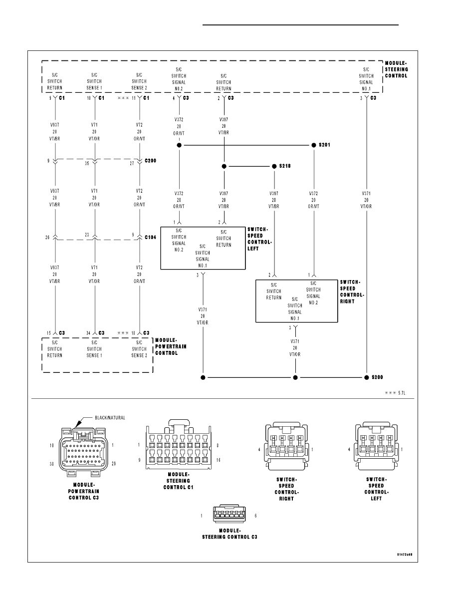
P0593-SPEED CONTROL SWITCH 2 CIRCUIT HIGH
9 - 684
ENGINE ELECTRICAL DIAGNOSTICS
WK
|
|
|
Content .. 1020 1021 1022 1023 ..
P0593-SPEED CONTROL SWITCH 2 CIRCUIT HIGH 9 - 684 ENGINE ELECTRICAL DIAGNOSTICS WK |