Content .. 1015 1016 1017 1018 ..
Jeep Grand Cherokee WK. Manual - part 1017
P0586-SPEED CONTROL VENT CONTROL CIRCUIT (CONTINUED)
2.
(V30) S/C BRAKE SWITCH OUTPUT CIRCUIT
Turn the ignition off.
Disconnect the S/C Servo harness connector.
Ignition on, engine not running.
Using the scan tool, actuate the S/C Vent Solenoid.
Using a test light connected to ground, probe the (V30) S/C Brake
Switch Output circuit in the S/C Servo harness connector.
Does the test light illuminate brightly and flash on and off?
Yes
>> Go To 5
No
>> Go To 3
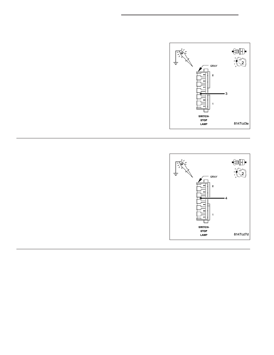
3.
(V32) S/C SUPPLY CIRCUIT
Turn the ignition off.
Connect the S/C Servo harness connector.
Disconnect the Stop Lamp Switch harness connector.
Ignition on, engine not running.
Using the scan tool, actuate the S/C Vent Solenoid.
Using a test light connected to ground, probe the (V32) S/C Supply
circuit in the Stop Lamp Switch harness connector.
Does the test light illuminate brightly?
Yes
>> Go To 4
No
>> Go To 8
9 - 664
ENGINE ELECTRICAL DIAGNOSTICS
WK