Jeep Grand Cherokee WK. Manual - part 101


  Index      Jeep     Jeep Grand Cherokee WK - service repair manual 2005 year


Search            


Content   ..  99  100  101  102   ..


Jeep Grand Cherokee WK. Manual - part 101


MASTER CYLINDER

DESCRIPTION

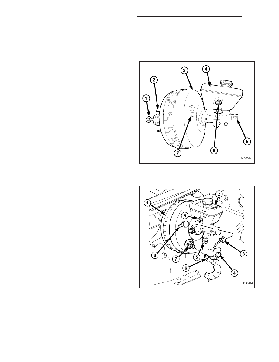
BASE MASTER CYLINDER WITHOUT ESP

The master cylinder body (5) is made of aluminum
and contains a primary and secondary piston assem-
bly. The cylinder body including the piston assemblies
are not serviceable. If diagnosis indicates an internal
problem with the cylinder body (5), it must be replaced
as an assembly. The master cylinder has a removable
reservoir (4) and fluid level indicator (6). The reservoir,
reservoir grommets, reservoir cap and fluid level
switch are the only replaceable parts on the master
cylinder.

MASTER CYLINDER WITH ESP

The master cylinder body is made of aluminum and
contains a primary and secondary piston assembly.
The cylinder body including the piston assemblies are
not serviceable. If diagnosis indicates an internal prob-
lem with the cylinder body, it must be replaced as an
assembly. The master cylinder with ESP has a pres-
sure switch (5) on the master cylinder. The reservoir
(2), reservoir grommets, reservoir cap, pressure switch
(5), solenoid connector (7) and fluid level switch (9)
are the only replaceable parts on the master cylinder.

OPERATION

The master cylinder bore contains a primary and secondary piston. The primary piston supplies hydraulic pressure
to the front brakes. The secondary piston supplies hydraulic pressure to the rear brakes. The master cylinder res-
ervoir stores reserve brake fluid for the hydraulic brake circuits.

5 - 30

BRAKES - BASE - SERVICE INFORMATION

WK

DIAGNOSIS AND TESTING

MASTER CYLINDER/POWER BOOSTER

1. Start engine and check booster vacuum hose connections. A hissing noise indicates vacuum leak. Correct any

vacuum leak before proceeding.

2. Stop engine and shift transmission into Neutral.

3. Pump brake pedal until all vacuum reserve in booster is depleted.

4. Press and hold brake pedal under light foot pressure. The pedal should hold firm, if the pedal falls away master

cylinder is faulty (internal leakage).

5. Start engine and note pedal action. It should fall away slightly under light foot pressure then hold firm. If no pedal

action is discernible, power booster, vacuum supply, or vacuum check valve is faulty. Proceed to the POWER
BOOSTER VACUUM TEST.

6. If the POWER BOOSTER VACUUM TEST passes, rebuild booster vacuum reserve as follows: Release brake

pedal. Increase engine speed to 1500 rpm, close the throttle and immediately turn off ignition to stop engine.

7. Wait a minimum of 90 seconds and try brake action again. Booster should provide two or more vacuum assisted

pedal applications. If vacuum assist is not provided, booster is faulty.

POWER BOOSTER VACUUM TEST

1. Connect vacuum gauge (6) to booster check valve

(4) with short length of hose (3) and T-fitting (2).

2. Start and run engine at curb idle speed for one

minute.

3. Observe the vacuum supply. If vacuum supply is

not adequate, repair vacuum supply.

4. Clamp (1) hose (7) shut between intake vacuum

source (5) and check valve (4).

5. Stop engine and observe vacuum gauge (6).

6. If vacuum drops more than one inch HG (33 milli-

bars) within 15 seconds, booster diaphragm or
check valve is faulty.

WK

BRAKES - BASE - SERVICE INFORMATION

5 - 31

POWER BOOSTER CHECK VALVE TEST

1. Disconnect vacuum hose from check valve (1).

2. Remove check valve (1) and valve seal (2) from

booster (3).

3. Use a hand operated vacuum pump for test.

4. Apply 15-20 inches vacuum at large end of check

valve.

5. Plug off the small end to prevent vacuum leakage.

6. Vacuum should hold steady. If gauge on pump indi-

cates vacuum loss, check valve is faulty and
should be replaced.

STANDARD PROCEDURE

MASTER CYLINDER BLEEDING

A new master cylinder should be bled before installa-
tion on the vehicle. Required bleeding tools include
bleed tubes and a wood dowel to stroke the pistons.
Bleed tubes can be fabricated from brake line.

1. Mount master cylinder in vise.

2. Attach bleed tubes to cylinder outlet ports (1). Then

position each tube end into reservoir (2).

3. Fill reservoir with fresh brake fluid.

4. Press cylinder pistons inward with wood dowel.

Then release pistons and allow them to return
under spring pressure. Continue bleeding opera-
tions until air bubbles are no longer visible in fluid.

REMOVAL

1. Siphon the master cylinder.

2. Remove the primary brake tube at the master cylinder.

3. Remove the primary brake tube from the HCU.

4. Remove the secondary brake tube at the master cylinder.

5. Remove the secondary brake tube at the HCU

6. Disconnect the brake fluid level switch from the master cylinder.

7. Remove the 2 master cylinder mounting nuts.

8. Remove the master cylinder.

5 - 32

BRAKES - BASE - SERVICE INFORMATION

WK

INSTALLATION

NOTE: Bleed new master cylinder on bench before installation.

1. Install the master cylinder with new gasket and nuts.

2. Reconnect the brake fluid level electrical connector.

3. Install the secondary brake tube at the HCU.

4. Install the secondary brake tube at the master cylinder.

5. Install the primary brake tube at the HCU.

6. Install the primary brake tube at the master cylinder.

7. Fill and bleed brake system.

PEDAL

DESCRIPTION

NON—ADJUSTABLE PEDAL

A suspended-type brake pedal is used, the pedal pivots on a shaft mounted in the pedal support bracket. The
bracket is attached to the dash panel.

The brake pedal assembly and pedal pad are the only serviceable component.

ADJUSTABLE PEDALS

The Adjustable Pedals System (APS) is designed to
enable the fore and aft repositioning of the brake and
accelerator pedals. This results in improved ergonom-
ics in relation to the steering wheel for taller and
shorter drivers. Being able to adjust the pedal posi-
tions also allows the driver to set steering wheel tilt
and seat position to the most comfortable position.
The position of the brake (4) and accelerator pedals
(3) can be adjusted without compromising safety or
comfort in actuating the pedals. Repositioning the ped-
als does not change the effort required for actuation.

Change of pedal position is accomplished by means
of a motor driven screw (5). Operating the adjustable
pedal switch activates the pedal drive motor (5). The
pedal drive motor turns a screw that changes the posi-
tion of the brake (4) and accelerator pedals (3). The
pedal can be moved rearward (closer to the driver) or
forward (away from driver). The brake pedal is moved
on its drive screw to a position where the driver feels
most comfortable.

The accelerator pedal (3) is moved at the same time and the same distance as the brake pedal. The accelerator
pedal adjustment screw is turned by a flexible shaft slaved off the brake adjustment screw.

Neither the pedal drive motor nor drive mechanism are subject to the mechanical stress of brake or accelerator
application.

SYSTEM FEATURES:

Range of Adjustment: The pedals may be adjusted up to 3 in. (75 mm)

Pedal Adjustment Speed: 0.5 in./sec (12.5 mm/sec)

Pedal Adjustment Inhibitors: Pedal adjustment is inhibited when the vehicle is in reverse or when

cruise control is activated.

Memory: An optional memory feature is available. This allows storing of one or two preferred pedal

positions in the Adjustable Pedal Module (APM). A preferred position can be stored and recalled

WK

BRAKES - BASE - SERVICE INFORMATION

5 - 33


Content   ..  99  100  101  102   ..