Jeep Grand Cherokee WJ. Manual - part 890


  Index      Jeep     Jeep Grand Cherokee WJ - service repair manual 2001 year


Search            


Content   ..  888  889  890  891   ..


Jeep Grand Cherokee WJ. Manual - part 890


(37) Remove the transmission and torque con-

verter from the vehicle.

DISASSEMBLY

(1) Clean transmission exterior with steam gun or

with solvent. Wear eye protection during cleaning
operations.

(2) Place transmission in a vertical position.
(3) Measure input shaft end play as follows (Fig.

21).

(a) Attach Adapter 8266-6 to Handle 8266-8.
(b) Attach

dial

indicator

C-3339

to

Handle

8266-8.

(c) Install the assembled tool onto the input

shaft of the transmission and tighten the retaining
screw on Adapter 8266-6 to secure it to the input
shaft.

(d) Position the dial indicator plunger against a

flat spot on the oil pump and zero the dial indica-
tor.

(e) Move the input shaft in and out. Record the

maximum travel for assembly reference.

(4) Remove shift and throttle levers from valve

body manual lever shaft.

(5) Place transmission in horizontal position.
(6) Remove transmission oil pan and gasket.
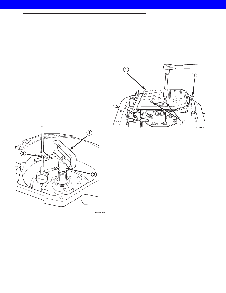
(7) Remove filter from valve body (Fig. 22). Keep

filter screws separate from other valve body screws.
Filter screws are longer and should be kept with fil-
ter.

(8) Remove park/neutral position switch.
(9) Remove hex head bolts attaching valve body to

transmission case (Fig. 23). A total of 10 bolts are
used. Note different bolt lengths for assembly refer-
ence.

(10) Remove valve body assembly. Push valve body

harness connector out of case. Then work park rod
and valve body out of case (Fig. 24).

(11) Remove accumulator piston and inner and

outer springs (Fig. 25).

(12) Remove pump oil seal with suitable pry tool

or slide-hammer mounted screw.

Fig. 21 Checking Input Shaft End Play

1 - TOOL 8266-8
2 - TOOL 8266-6
3 - TOOL C-3339

Fig. 22 Oil Filter Removal

1 - OIL FILTER
2 - VALVE BODY
3 - FILTER SCREWS (2)

WG

AUTOMATIC - 44RE

21s - 67

AUTOMATIC - 44RE (Continued)

2001 JEEP GRAND CHEROKEE

(13) Loosen front band adjusting screw locknut 4-5

turns. Then tighten band adjusting screw until band
is tight around front clutch retainer. This prevents
front/rear clutches from coming out with pump and
possibly damaging clutch or pump components.

(14) Remove oil pump bolts.
(15) Thread bolts of Slide Hammer Tools C-3752

into threaded holes in pump body flange (Fig. 26).

(16) Bump slide hammer weights outward to

remove pump and reaction shaft support assembly
from case (Fig. 26).

Fig. 23 Valve Body Bolt Locations

1 - VALVE BODY BOLTS
2 - VALVE BODY BOLTS

Fig. 24 Valve Body Removal

1 - GOVERNOR PRESSURE SENSOR
2 - VALVE BODY
3 - PARK ROD
4 - ACCUMULATOR PISTON
5 - GOVERNOR PRESSURE SOLENOID

Fig. 25 Accumulator Piston And Springs

1 - ACCUMULATOR PISTON
2 - OUTER SPRING
3 - INNER SPRING

Fig. 26 Removing Oil Pump And Reaction Shaft

Support Assembly

1 - OIL PUMP AND REACTION SHAFT SUPPORT ASSEMBLY
2 - SLIDE HAMMER TOOLS C-3752

21s - 68

AUTOMATIC - 44RE

WG

AUTOMATIC - 44RE (Continued)

2001 JEEP GRAND CHEROKEE

(17) Loosen front band adjusting screw until band

is completely loose.

(18) Squeeze front band together and remove band

strut (Fig. 27).

(19) Remove front band lever (Fig. 28).
(20) Remove front band lever shaft plug, if neces-

sary, from converter housing.

(21) Remove front band lever shaft.

(22) Remove front and rear clutch units as assem-

bly. Grasp input shaft, hold clutch units together and
remove them from case (Fig. 29).

(23) Lift front clutch off rear clutch (Fig. 30). Set

clutch units aside for overhaul.

(24) Remove intermediate shaft thrust washer

from front end of shaft or from rear clutch hub (Fig.
31).

Fig. 27 Removing Front Band Strut

1 - BAND LEVER
2 - BAND STRUT
3 - FRONT BAND

Fig. 28 Removing Front Band Lever

1 - FRONT BAND LEVER

Fig. 29 Removing Front/Rear Clutch Assemblies

1 - INPUT SHAFT
2 - FRONT CLUTCH
3 - REAR CLUTCH

Fig. 30 Separating Front/Rear Clutch Assemblies

1 - FRONT CLUTCH
2 - REAR CLUTCH

WG

AUTOMATIC - 44RE

21s - 69

AUTOMATIC - 44RE (Continued)

2001 JEEP GRAND CHEROKEE

(25) Remove output shaft thrust plate from inter-

mediate shaft hub (Fig. 32).

(26) Slide front band off driving shell (Fig. 33) and

remove band from case.

(27) Remove planetary geartrain as assembly (Fig.

34). Support geartrain with both hands during
removal. Do not allow machined surfaces on interme-
diate shaft or overdrive piston retainer to become
nicked or scratched.

(28) If overdrive unit is not to be serviced, install

Alignment Shaft 6227-2 into the overdrive unit to
prevent misalignment of the overdrive clutches dur-
ing service of main transmission components.

(29) Loosen rear band adjusting screw 4-5 turns.
(30) Remove low-reverse drum snap-ring (Fig. 35).
(31) Remove low-reverse drum and reverse band.
(32) Remove overrunning clutch roller and spring

assembly as a unit (Fig. 36).

(33) Compress front servo rod guide about 1/8 inch

with Valve Spring Compressor C-3422-B (Fig. 37).

(34) Remove front servo rod guide snap-ring. Exer-

cise caution when removing snap-ring. Servo bore
can be scratched or nicked if care is not exercised.

(35) Remove compressor tools and remove front

servo rod guide, spring and servo piston.

Fig. 31 Removing Intermediate Shaft Thrust Washer

1 - INTERMEDIATE SHAFT THRUST WASHER
2 - INPUT SHAFT
3 - REAR CLUTCH RETAINER HUB

Fig. 32 Removing Intermediate Shaft Thrust Plate

1 - INTERMEDIATE SHAFT HUB
2 - INTERMEDIATE SHAFT THRUST PLATE

Fig. 33 Front Band Removal

1 - DRIVING SHELL
2 - FRONT BAND

21s - 70

AUTOMATIC - 44RE

WG

AUTOMATIC - 44RE (Continued)

2001 JEEP GRAND CHEROKEE


Content   ..  888  889  890  891   ..