Jeep Grand Cherokee WJ. Manual - part 445
BAND ADJUSTMENTS
FRONT BAND ADJUSTMENT
The front (kickdown) band adjusting screw is
located on the left side of the transmission case
above the manual valve and throttle valve levers.
(1) Raise vehicle.
(2) Loosen band adjusting screw locknut (Fig. 320).
Then back locknut off 3-5 turns. Be sure adjusting
screw turns freely in case. Apply lubricant to screw
threads if necessary.
(3) Tighten band adjusting screw to 8 N·m (72 in.
lbs.)
torque
with
Inch
Pound
Torque
Wrench
C-3380-A, a 3-in. extension and appropriate Torx
y
socket.
CAUTION: If Adapter C-3705 is needed to reach the
adjusting screw, tighten the screw to only 5 N·m
(47-50 in. lbs.) torque.
(4) Back off front band adjusting screw 3 turns.
(5) Hold adjuster screw in position and tighten
locknut to 41 N·m (30 ft. lbs.) torque.
(6) Lower vehicle.
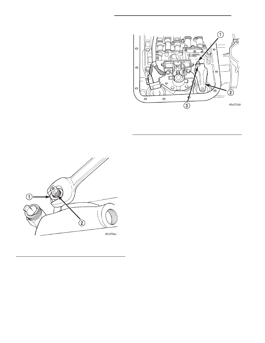
REAR BAND ADJUSTMENT
The transmission oil pan must be removed for
access to the rear band adjusting screw.
(1) Raise vehicle.
(2) Remove transmission oil pan and drain fluid.
(3) Loosen band adjusting screw locknut 5-6 turns
(Fig. 321). Be sure adjusting screw turns freely in
lever.
(4) Tighten adjusting screw to 8 N·m (72 in. lbs.)
torque.
(5) Back off adjusting screw 4 turns.
(6) Hold adjusting screw in place and tighten lock-
nut to 34 N·m (25 ft. lbs.) torque.
(7) Position new gasket on oil pan and install pan
on transmission. Tighten pan bolts to 17 N·m (13 ft.
lbs.) torque.
(8) Lower vehicle and refill transmission with
Mopar
t ATF Plus 3, Type 7176 fluid.
VALVE BODY
CONTROL PRESSURE ADJUSTMENTS
There are two control pressure adjustments on the
valve body;
• Line Pressure
• Throttle Pressure
Line and throttle pressures are interdependent
because each affects shift quality and timing. As a
result, both adjustments must be performed properly
and in the correct sequence. Adjust line pressure first
and throttle pressure last.
LINE PRESSURE ADJUSTMENT
Measure distance from the valve body to the inner
edge of the adjusting screw with an accurate steel
scale (Fig. 322).
Distance should be 33.4 mm (1-5/16 in.).
If adjustment is required, turn the adjusting screw
in, or out, to obtain required distance setting.
NOTE: The 33.4 mm (1-5/16 in.) setting is an
approximate setting. Manufacturing tolerances may
make it necessary to vary from this dimension to
obtain desired pressure.
One complete turn of the adjusting screw changes
line pressure approximately 1-2/3 psi (9 kPa).
Fig. 320 Front Band Adjustment Screw Location
1 – LOCK-NUT
2 – FRONT BAND ADJUSTER
Fig. 321 Rear Band Adjusting Screw Location
1 – ADJUSTING SCREW
2 – REAR BAND LEVER
3 – LOCKNUT
21 - 162
42RE AUTOMATIC TRANSMISSION
WJ
ADJUSTMENTS (Continued)