Jeep Grand Cherokee WJ. Manual - part 365


  Index      Jeep     Jeep Grand Cherokee WJ - service repair manual 2001 year


Search            


Content   ..  363  364  365  366   ..


Jeep Grand Cherokee WJ. Manual - part 365


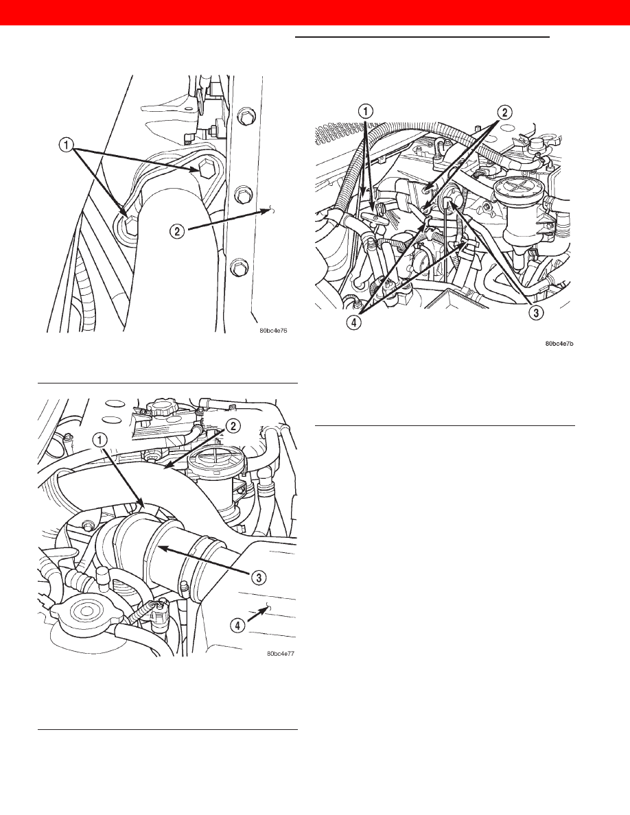
(10) Remove the EGR vacuum supply hose from

the EGR valve (Fig. 3).

(11) Disconnect the heater core coolant supply

lines from the engine assembly (Fig. 3).

(12) Unclip the wire harness from the coolant sup-

ply lines (Fig. 3).

(13) Remove the (2) EGR valve / coolant supply

line retaining bolts (Fig. 3).

(14) Remove

the

coolant

supply

line

support

bracket bolt from the water pump housing.

(15) Disconnect the two remaining hoses and

remove the coolant lines from the vehicle.

(16) Remove the oil separator retaining bolts.
(17) Disconnect the crankcase vapor supply and

return hoses and remove the oil separator from the
vehicle.

(18) Remove the transmission dipstick tube sup-

port bracket nut from the turbocharger heatshield
(Fig. 4).

(19) Remove the exhaust manifold / turbocharger

heatshield retaining bolts and remove the heatshield
from the vehicle.

(20) Pull back the EGR tube heatshield to access

and remove the EGR tube nut from the exhaust
manifold. Remove the EGR valve and tube assembly
from the vehicle.

Fig. 1 Exhaust System Inlet Pipe Retaining Bolts

1 – EXHAUST SYSTEM INLET PIPE RETAINING BOLTS
2 – ENGINE OIL PAN

Fig. 2 Air Intake Hoses

1 – BREATHER HOSE
2 – INTERCOOLER INLET HOSE
3 – FRESH AIR INLET TUBE
4 – AIR FILTER COVER

Fig. 3 Engine Compartment

1 – HEATER CORE COOLANT SUPPLY HOSES
2 – EGR VALVE/COOLANT SUPPLY LINE BRACKET RETAINING

BOLTS

3 – EGR VALVE VACUUM SUPPLY LINE
4 – WIRE HARNESS RETAINING CLIPS

11 - 2

EXHAUST SYSTEM AND TURBOCHARGER

WJ

REMOVAL AND INSTALLATION (Continued)

2000 JEEP GRAND CHEROKEE

(21) Remove the oil pressure supply line banjo bolt

from the turbocharger.

(22) Position a drain pan under the transmission.
(23) Remove the transmission dipstick tube from

the transmission oil pan by pulling straight up. Posi-
tion the tube assembly out of the way to allow for
manifold / turbocharger removal.

(24) Remove the exhaust manifold retaining nuts

and remove the manifold and turbocharger assembly
from the vehicle (Fig. 6).

NOTE: If only servicing the intake manifold the fol-
lowing two steps are not required.

(25) Place the assembly in a vice.
(26) Remove the (4) turbocharger to exhaust man-

ifold retaining nuts and separate.

(27) Remove the (4) intake air duct retaining bolts

from the intake manifold.

(28) Remove the remaining bolts from the intake

air duct and position the duct and hose assembly out
of the way.

(29) Remove the intake manifold retaining bolts

and remove the intake manifold from the vehicle
(Fig. 6).

(30) Remove the intake/exhaust manifold gasket

from the manifolds mounting studs.

CLEANING

All old gaskets should be inspected for any tears or

signs of prior leakage. If any gaskets show such indi-
cations, they should be replaced with new gaskets.
All gasket mating surfaces must be cleaned of old
gasket material to produce a smooth and dirt/oil free
sealing surface for the new gasket.

INSTALLATION

(1) Position the new intake/exhaust manifold gas-

ket on the manifolds mounting studs.

(2) Install the intake manifold and install the

retaining nuts (Fig. 6). Torque the nuts to 32 N·m (23
ft. lbs.).

(3) Position the new intake air duct gasket.
(4) Install the intake air duct on the engine.

Torque the bolts to 32 N·m (23 ft. lbs.).

NOTE: If only servicing the intake manifold the fol-
lowing two steps are not required.

Fig. 4 Transmission Dipstick Tube Support Bracket

1 – TRANSMISSION DIPSTICK TUBE
2 – TURBOCHARGER EXHAUST MANIFOLD HEATSHIELD
3 – TRANSMISSION DIPSTICK TUBE SUPPORT BRACKET

RETAINING NUT

Fig. 5 Exhaust Manifold/Turbocharger Heatshield

1 – EXHAUST MANIFOLD/TURBOCHARGER HEATSHIELD
2 – HEATSHIELD RETAINING BOLTS
3 – HEATER CORE SUPPLY/RETURN LINES
4 – OIL FILTER HOUSING
5 – ENGINE OIL COOLER
6 – TURBOCHARGER

WJ

EXHAUST SYSTEM AND TURBOCHARGER

11 - 3

REMOVAL AND INSTALLATION (Continued)

2000 JEEP GRAND CHEROKEE

(5) Position the gasket and install the turbo on the

exhaust manifold. Torque the nuts to 32 N·m (23 ft.
lbs.).

(6) Remove the assembly from the vice and posi-

tion on the exhaust manifold mounting studs.

(7) Install the exhaust manifold retaining nuts and

torque to 32 N·m (23 ft. lbs.) (Fig. 6).

(8) Install the transmission dipstick tube in the

transmission case.

(9) Remove the drain pan.
(10) Install the oil pressure supply line on turbo-

charger. Torque the banjo bolt fitting to 27 N·m (20
ft. lbs.). Be certain the copper sealing washers are
installed. One on the top and bottom of the supply
line.

(11) Install the EGR tube nut on the exhaust man-

ifold and temporarily install one of the EGR valve
retaining bolts. Be certain the EGR valve gasket is in
place.

(12) Torque the EGR tube retaining nut to 34 N·m

(25 ft.lbs.). Remove the temporarily installed EGR
valve bolt

(13) Install the exhaust manifold heatshield (Fig.

5). Torque bolts to 11 N·m (97 in. lbs.).

(14) Install the transmission dipstick tube support

bracket retaining nut on the turbocharger heatshield
(Fig. 7). Torque the nut to 20 N·m (177 in. lbs.).

(15) Install the front (front of engine) heater core

coolant supply hoses on the coolant line assembly
and install the line assembly on the engine. Torque
the (3) retaining bolts to 27 N·m (20 ft. lbs.) (Fig. 8).

(16) Connect the crankcase vapor supply and

return hoses on the oil separator.

(17) Install the oil separator retaining bolts.
(18) Install the heater core coolant supply hoses on

the coolant line assembly (Fig. 8).

(19) Clip the wire harness on the coolant supply

lines (Fig. 8).

(20) Install the EGR vacuum supply hose on the

EGR valve.

Fig. 6 Intake and Exhaust Manifold

1 – WATER MANIFOLD
2 – INTAKE MANIFOLD ELBOW
3 – BOOST PRESSURE SENSOR
4 – INTAKE MANIFOLD
5 – INTAKE/EXHAUST MANIFOLD GASKET
6 – TURBOCHARGER OIL RETURN LINE
7 – EXHAUST MANIFOLD
8 – CYLINDER HEAD

Fig. 7 Transmission Dipstick Tube Support Bracket

1 – TRANSMISSION DIPSTICK TUBE
2 – TURBOCHARGER EXHAUST MANIFOLD HEATSHIELD
3 – TRANSMISSION DIPSTICK TUBE SUPPORT BRACKET

RETAINING NUT

11 - 4

EXHAUST SYSTEM AND TURBOCHARGER

WJ

REMOVAL AND INSTALLATION (Continued)

2000 JEEP GRAND CHEROKEE

(21) Install the fresh air inlet tube assembly on

the turbocharger. Clip the air filter cover in position
and connect the breather hose (Fig. 9).

(22) Install the intercooler inlet hose on the vehi-

cle (Fig. 9).

(23) Raise the vehicle on the hoist.
(24) Install the turbocharger oil return hose on the

turbocharger.

(25) Install the exhaust system inlet pipe on the

turbocharger (Fig. 10). Torque the bolts to 22 N·m
(194 in. lbs.).

(26) Lower the vehicle on the hoist.
(27) Fill the cooling system. Refer to Group 7,

Cooling System for procedure.

(28) Check the transmission fluid level and top off

if necessary.

(29) Connect the negative battery cable.
(30) Start the engine and check for leaks.

TURBOCHARGER

REMOVAL

(1) Disconnect the negative battery cable
(2) Raise the vehicle on a hoist.

WARNING: DO NOT LOOSEN THE RADIATOR VENT
OR DRAINCOCK WITH THE SYSTEM HOT AND
PRESSURIZED. SERIOUS BURNS FROM COOLANT
CAN OCCUR

Fig. 8 Diesel Engine Compartment

1 – HEATER CORE COOLANT SUPPLY HOSES
2 – EGR VALVE/COOLANT SUPPLY LINE BRACKET RETAINING

BOLTS

3 – EGR VALVE VACUUM SUPPLY LINE
4 – WIRE HARNESS RETAINING CLIPS

Fig. 9 Air Intake Hoses

1 – BREATHER HOSE
2 – INTERCOOLER INLET HOSE
3 – FRESH AIR INLET TUBE
4 – AIR FILTER COVER

Fig. 10 Exhaust System Inlet Pipe Retaining Bolts

1 – EXHAUST SYSTEM INLET PIPE RETAINING BOLTS
2 – ENGINE OIL PAN

WJ

EXHAUST SYSTEM AND TURBOCHARGER

11 - 5

REMOVAL AND INSTALLATION (Continued)

2000 JEEP GRAND CHEROKEE


Content   ..  363  364  365  366   ..