Jeep Grand Cherokee WJ. Manual - part 328


  Index      Jeep     Jeep Grand Cherokee WJ - service repair manual 2001 year


Search            


Content   ..  326  327  328  329   ..


Jeep Grand Cherokee WJ. Manual - part 328


PISTONS—FITTING

BORE GAGE METHOD
(1) To correctly select the proper size piston, a cyl-

inder bore gauge, capable of reading in 0.003 mm
(.0001 in.) INCREMENTS is required. If a bore
gauge is not available, do not use an inside microme-
ter.

(2) Measure the inside diameter of the cylinder

bore at a point 49.5 mm (1-15/16 inches) below top of
bore. Start perpendicular (across or at 90 degrees) to
the axis of the crankshaft at point A and then take
an additional bore reading 90 degrees to that at point
B (Fig. 13).

(3) The coated pistons will be serviced with the

piston pin and connecting rod pre-assembled. Tin
coated pistons should not be used as replacements for
coated pistons.

(4) The coating material is applied to the piston

after the final piston machining process. Measuring
the outside diameter of a coated piston will not pro-
vide accurate results (Fig. 12). Therefore measuring
the inside diameter of the cylinder bore with a dial
Bore Gauge is MANDATORY. To correctly select the
proper size piston, a cylinder bore gauge capable of
reading in 0.003 mm (.0001 in.) increments is
required.

(5) Piston

installation

into

the

cylinder

bore

requires slightly more pressure than that required
for non-coated pistons. The bonded coating on the
piston will give the appearance of a line-to-line fit
with the cylinder bore.

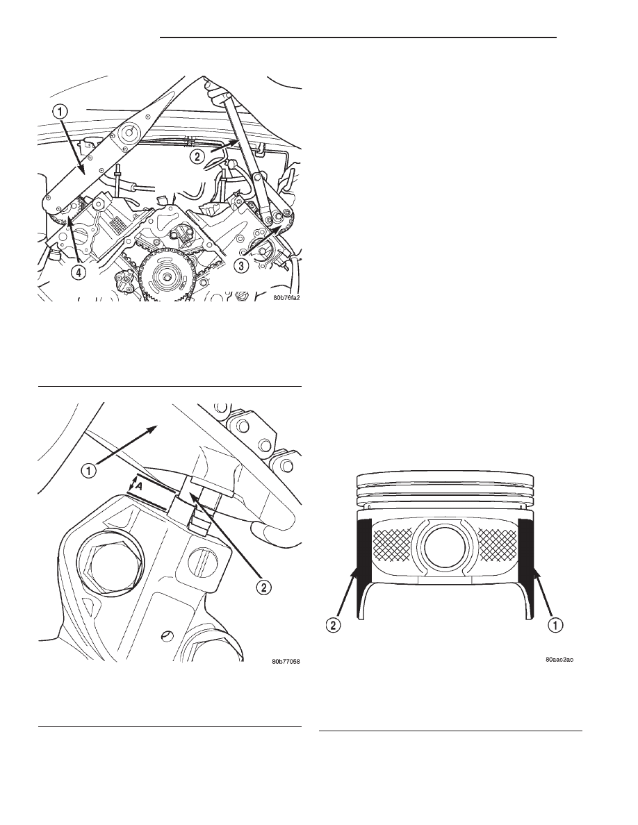
Fig. 10 Camshaft Sprocket Installation—Right

Cylinder Head

1 – TORQUE WRENCH
2 – SPECIAL TOOL 6958 WITH ADAPTER PINS 8346
3 – LEFT CAMSHAFT SPROCKET
4 – RIGHT CAMSHAFT SPROCKET

Fig. 11 Measuring Secondary Timing Chains For

Stretch

1 – SECONDARY TENSIONER ARM
2 – SECONDARY CHAIN TENSIONER PISTON

Fig. 12 Moly Coated Piston

1 – MOLY COATED
2 – MOLY COATED

9 - 78

4.7L ENGINE

WJ

SERVICE PROCEDURES (Continued)

PISTON RINGS—FITTING

RING END GAP
Before reinstalling used rings or installing new

rings, the ring clearances must be checked.

(1) Wipe the cylinder bore clean.
(2) Insert the ring in the cylinder bore.

NOTE: The ring gap measurement must be made
with the ring positioned at least 12mm (0.50 inch.)
from bottom of cylinder bore.

(3) Using a piston, to ensure that the ring is

squared in the cylinder bore, slide the ring downward
into the cylinder.

(4) Using a feeler gauge check the ring end gap

(Fig. 14). Replace any rings not within specification.

PISTON RING SIDE CLEARANCE

NOTE: Make sure the piston ring grooves are clean
and free of nicks and burrs.

(5) Measure the ring side clearance as shown (Fig.

15) make sure the feeler gauge fits snugly between
the ring land and the ring. Replace any ring not
within specification.

(6) Rotate the ring around the piston, the ring

must rotate in the groove with out binding.

EARLY BUILD

(7) The No. 1 and No. 2 piston rings have a differ-

ent cross section. Ensure No. 2 ring is installed with
manufacturers I. D. mark (Dot) facing up, towards
top of the piston.

LATE BUILD

The No. 1 and No. 2 piston rings have a different

cross section. Ensure No. 2 ring is installed with
manufacturers I.D. mark (Dot) facing up, towards top
of the piston. On late build engines the piston top
ring groove and crown are not anodized therefore,
the No. 1 piston ring is coated with an anti-friction
coating. Care must be used to ensure that when
installing piston rings on late build engines that the
correct No. 1 piston ring be installed, failure to use
the correct piston ring can cause severe damage to
the piston and/or cylinder block.

Fig. 13 Bore Gauge—Typical

1 – FRONT
2 – BORE GAUGE
3 – CYLINDER BORE
4 – 49.5 MM (1–15/16 in)

Fig. 14 Ring End Gap Measurement—Typical

1 – FEELER GAUGE

Fig. 15 Measuring Piston Ring Side Clearance

1 – FEELER GAUGE

WJ

4.7L ENGINE

9 - 79

SERVICE PROCEDURES (Continued)

2000 WJ Service Manual
Publication No. 81-370-0047
TSB 26-12-99

December, 1999

NOTE: Piston rings are installed in the following order:

Oil ring expander.

Upper oil ring side rail.

Lower oil ring side rail.

No. 2 Intermediate piston ring.

No. 1 Upper piston ring.

(8) Install the oil ring expander.
(9) Install upper side rail (Fig. 16) by placing one

end between the piston ring groove and the expander
ring. Hold end firmly and press down the portion to
be installed until side rail is in position. Repeat this
step for the lower side rail.

(10) Install No. 2 intermediate piston ring using a

piston ring installer (Fig. 17).

(11) Install No. 1 upper piston ring using a piston

ring installer (Fig. 17).

(12) Position piston ring end gaps as shown in

(Fig. 18). It is important that expander ring gap is at
least 45° from the side rail gaps, but not on the pis-
ton pin center or on the thrust direction.

CONNECTING ROD BEARINGS—FITTING

Inspect the connecting rod bearings for scoring and

bent alignment tabs (Fig. 19) (Fig. 20). Check the
bearings for normal wear patterns, scoring, grooving,
fatigue and pitting (Fig. 21). Replace any bearing
that shows abnormal wear.

Inspect the connecting rod journals for signs of

scoring, nicks and burrs.

Misaligned or bent connecting rods can cause abnor-

mal wear on pistons, piston rings, cylinder walls, con-
necting rod bearings and crankshaft connecting rod
journals. If wear patterns or damage to any of these
components indicate the probability of a misaligned con-

necting rod, inspect it for correct rod alignment. Replace
misaligned, bent or twisted connecting rods.

(1) Wipe the oil from the connecting rod journal.
(2) Lubricate the upper bearing insert and install

in connecting rod.

(3) Use piston ring compressor and Guide Pins

Special Tool 8507 (Fig. 22) to install the rod and pis-
ton assemblies. The oil slinger slots in the rods must
face front of the engine. The “F”’s near the piston
wrist pin bore should point to the front of the engine.

(4) Install the lower bearing insert in the bearing

cap. The lower insert must be dry. Place strip of Plas-
tigage across full width of the lower insert at the cen-
ter of bearing cap. Plastigage must not crumble in
use. If brittle, obtain fresh stock.

(5) Install bearing cap and connecting rod on the

journal and tighten bolts to 27 N·m (20 ft. lbs.) plus a
90° turn. DO NOT rotate crankshaft. Plastigage will
smear, resulting in inaccurate indication.

(6) Remove the bearing cap and determine amount

of bearing-to-journal clearance by measuring the
width of compressed Plastigage (Fig. 23). Refer to

PISTON RING SPECIFICATION CHART

Ring Position

Groove

Maximum

Clearance

Clearance

Upper Ring

.051-.094mm

0.11mm

(0.0020-.0037 in.)

(0.004 in.)

Intermediate

Ring

0.04-0.08mm

0.10mm

(00016-0.0031 in.)

(0.004 in.)

Oil Control Ring

.019-.229mm

.25mm

(Steel Rails)

(.0007-.0090 in.)

(0.010 in.)

Ring Position

Ring Gap

Wear Limit

Upper Ring

0.20-0.36mm

0.40mm

(0.008-0.014 in.)

(0.0016in.)

Intermediate

Ring

0.37-0.63mm

0.71mm

(0.014-0.025 in.)

(0.028in.)

Oil Control Ring

0.025-0.76mm

1.52mm

(Steel Rail)

(0.010- 0.030 in.)

(0.060in.)

Fig. 16 Side Rail—Installation

1 – SIDE RAIL END

Fig. 17 Upper and Intermediate Rings—Installation

9 - 80

4.7L ENGINE

WJ

SERVICE PROCEDURES (Continued)

2000 WJ Service Manual
Publication No. 81-370-0047
TSB 26-12-99

December, 1999

Engine Specifications for the proper clearance. Plas-
tigage

should

indicate

the

same

clearance

across the entire width of the insert. If the
clearance varies, it may be caused by either a
tapered journal, bent connecting rod or foreign
material trapped between the insert and cap or
rod.

(7) If the correct clearance is indicated, replace-

ment of the bearing inserts is not necessary. Remove
the Plastigage from crankshaft journal and bearing
insert. Proceed with installation.

(8) If

bearing-to-journal

clearance

exceeds

the

specification, determin which services bearing set to
use the bearing sizes are as follows:

(9) Repeat the Plastigage measurement to verify

your bearing selection prior to final assembly.

(10) Once you have selected the proper insert,

install the insert and cap. Tighten the connecting rod
bolts to 27 N·m (20 ft. lbs.) plus a 90° turn.

Slide snug-fitting feeler gauge between the con-

necting rod and crankshaft journal flange (Fig. 24).
Refer to Engine Specifications for the proper clear-
ance. Replace the connecting rod if the side clearance
is not within specification.

CRANKSHAFT MAIN BEARINGS

INSPECTION

Wipe the inserts clean and inspect for abnormal

wear patterns and for metal or other foreign material
imbedded in the lining. Normal main bearing insert
wear patterns are illustrated (Fig. 25).

Fig. 18 Piston Ring End Gap Position

1 – SIDE RAIL UPPER
2 – NO. 1 RING GAP
3 – PISTON PIN
4 – SIDE RAIL LOWER
5 – NO. 2 RING GAP AND SPACER EXPANDER GAP

Fig. 19 Connecting Rod Bearing Inspection

1 – UPPER BEARING HALF
2 – MATING EDGES
3 – GROOVES CAUSED BY ROD BOLTS SCRATCHING

JOURNAL DURING INSTALLATION

4 – WEAR PATTERN — ALWAYS GREATER ON UPPER

BEARING

5 – LOWER BEARING HALF

Fig. 20 Locking Tab Inspection

1 – ABNORMAL CONTACT AREA CAUSED BY LOCKING TABS

NOT FULLY SEATED OR BEING BENT

Fig. 21 Scoring Caused by Insufficient Lubrication

or by Damaged Crankshaft Pin Journal

WJ

4.7L ENGINE

9 - 81

SERVICE PROCEDURES (Continued)


Content   ..  326  327  328  329   ..