Content .. 1157 1158 1159 1160 ..
Jeep Grand Cherokee WJ. Manual - part 1159
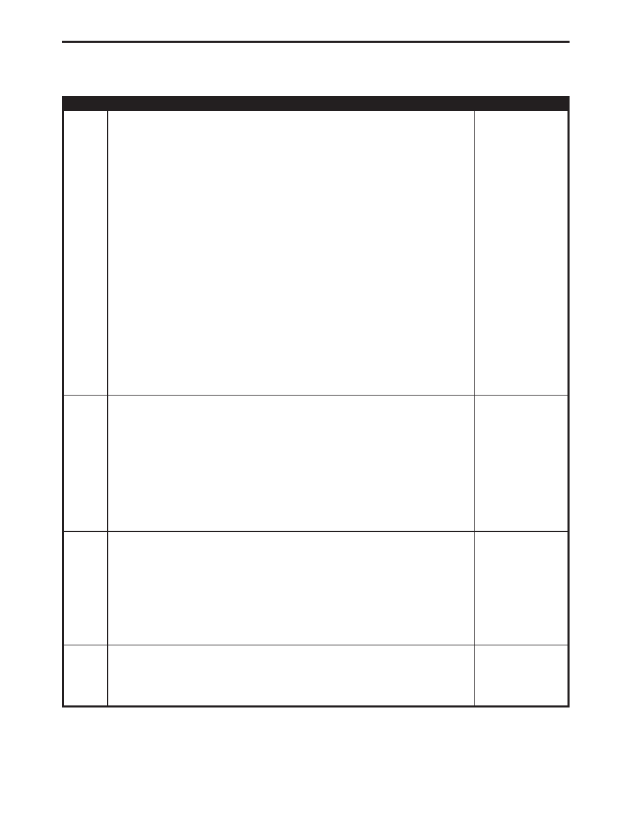
TEST
ACTION
APPLICABILITY
2
Use Scope input cable CH7058, Cable to Probe adapter CH7062, and the red and
black test probes.
Connect the scope input cable to the channel one connector on the DRB. Attach the
red and black leads and the cable to probe adapter to the scope input cable.
Select DRB Standalone.
Select lab scope.
Select Live.
Select 12 volt square wave.
Press F2 for Scope.
Press F2 and use the down arrow to set voltage range to 20 volts. Press F2 again
when complete.
Disconnect the CD Changer harness connector (DIN cable).
Connect the Black lead to the chassis ground. Connect the Red lead to the PCI Bus
circuit in the CD Changer DIN Cable connector.
Turn the ignition on.
Turn the Radio and CD Changer on.
Observe the voltage display on the DRB Lab Scope.
What is the voltage displayed on the scope?
All
Pulse from 0 to approximately 7.5 volts
Steady 0 volts
Repair the PCI Bus circuit for an open.
Perform BODY VERIFICATION TEST - VER 1.
3
Turn the ignition off.
Disconnect the CD Changer harness connector (DIN cable).
Turn the ignition on.
Turn the Radio and the CD Changer on.
Using a 12-volt test light connected to ground, probe the ignition switch output
circuit in the CD Changer DIN Cable connector.
Is the test light illuminated?
All
Yes
→
No
→
Replace the Radio.
Perform BODY VERIFICATION TEST - VER 1.
4
Turn the ignition off.
Disconnect the CD Changer harness connector (DIN cable).
Using a 12-volt test light connected to 12-volts, probe the CD Changer ground circuit
in the CD Changer connector (DIN cable).
Is the test light illuminated?
All
Yes
→
No
→
Replace the Radio.
Perform BODY VERIFICATION TEST - VER 1.
5
If there are no possible causes remaining, view repair.
All
Repair
Replace the CD Changer.
Perform BODY VERIFICATION TEST - VER 1.
139
COMMUNICATION
NO PCI MESSAGES FROM CD CHANGER —
Continued