Content .. 1029 1030 1031 1032 ..
Jeep Grand Cherokee WJ. Manual - part 1031
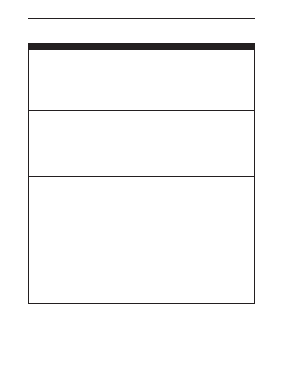
TEST
ACTION
APPLICABILITY
11
Turn the ignition off to the lock position.
Disconnect the PCM harness connectors.
Disconnect the Transmission Solenoid Assembly harness connector.
Ignition on, engine not running.
Measure the voltage of the Governor Pressure Solenoid Control circuit.
Is the voltage above 0.5 volt?
without 45RFE
AUTO TRANS
Yes
→
Repair the Governor Solenoid Control circuit for a short to
voltage.
Perform TRANSMISSION VERIFICATION TEST VER - 1.
No
→
12
Turn the ignition off to the lock position.
Disconnect the PCM harness connectors.
Disconnect the Transmission Solenoid Assembly harness connector.
Remove the Transmission Control Relay.
Check connectors - Clean/repair as necessary
Measure the resistance between the Governor Pressure Solenoid Control circuit and
all other circuits in the Transmission Solenoid Assembly harness connector.
Is the resistance below 100 kohms between any two circuits?
without 45RFE
AUTO TRANS
Yes
→
Repair as necessary.
Perform TRANSMISSION VERIFICATION TEST VER - 1.
No
→
13
Turn the ignition off to the lock position.
Disconnect the PCM harness connectors.
Remove the Transmission Control Relay.
Measure the resistance of the Governor Pressure Solenoid Control circuit between
the PCM harness connector and the Transmission Control Relay Output circuit
connector.
Is the resistance between 3.0 ohms and 6.0 ohms
without 45RFE
AUTO TRANS
Yes
→
No
→
Replace the Transmission Solenoid Assembly in accordance with
the Service Information.
Perform TRANSMISSION VERIFICATION TEST VER - 1.
14
Turn the ignition off to the lock position.
Disconnect the PCM harness connectors.
Check connectors - Clean/repair as necessary
Measure the resistance between the Governor Pressure Solenoid Control circuit and
ground.
Is the resistance below 5.0 ohms?
without 45RFE
AUTO TRANS
Yes
→
Repair or Replace the Transmission Solenoid Assembly for a short
to ground.
Perform TRANSMISSION VERIFICATION TEST VER - 1.
No
→
341
TRANSMISSION
P0748-PRESSURE SOL CONTROL/TRANS RELAY CIRCUITS —
Continued