Jaguar X-Type Sedan and Estate (Wagon). Manual - part 677


  Index      Jaguar     Jaguar X-Type Sedan and Estate (Wagon) (2.0 L, 2.5 L and 3.0 L Gasoline; 2.0 L and 2.2 L, Diesel) - manual 2001-2009 year


Search            


Content   ..  675  676  677  678   ..


Jaguar X-Type Sedan and Estate (Wagon). Manual - part 677


Published: 11-May-2011

Supplemental Restraint System - Air Bag Supplemental Restraint System (SRS)

Description and Operation

WARNING: All pyrotechnic devices are dangerous. Before performing any procedures on any pyrotechnic device, read all information

contained within the Standard W orkshop Practices section of this manual.
For additional information, refer to: 

Standard W orkshop Practices

 (100-00 General Information, Description and Operation).

The SRS is designed to provide increased collision protection for front seat occupants in addition to that provided by the three-point safety
belt system. Safety belt use is necessary to obtain the best occupant protection and to receive the full advantages of the SRS.

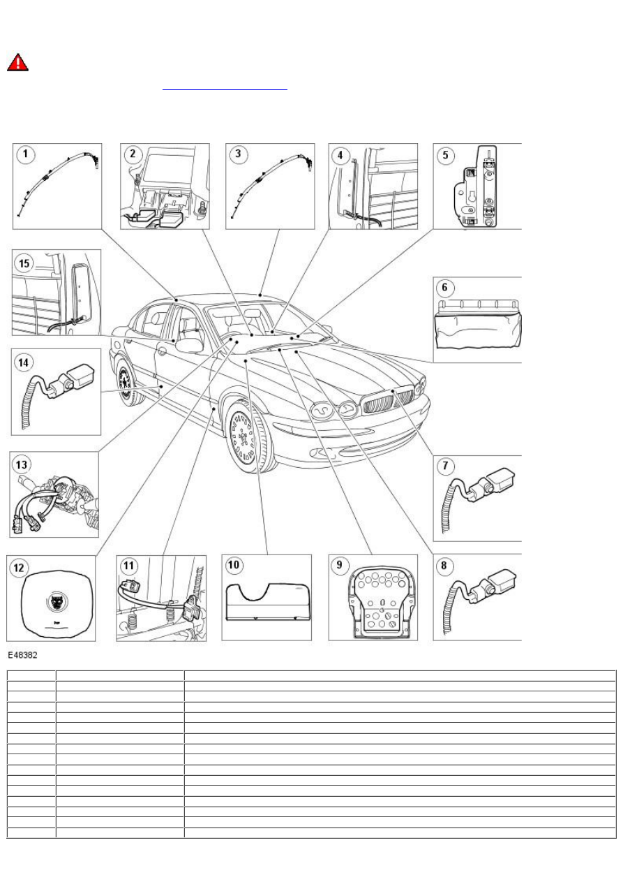
Air Bag Supplemental Restraint System (SRS) Components

Item

Part Number

Description

1

Side air curtain module

2

Restraints control module (RCM)

3

Side air curtain module

4

Side air bag module

5

Passenger air bag deactivation (PAD) indictor

6

Passenger air bag module

7

Crash sensor

8

Side impact sensor

9

Passenger weight sensor

10

Driver lower air bag module

11

Seat track position sensor

12

Driver air bag module

13

Air bag sliding contact

14

Side impact sensor

15

-

Side air bag module

Restraints Control Module (RCM)

The restraints control module (RCM):

The primary purpose of the restraints control system is to discriminate between an event that warrants supplemental restraints
system deployment and an event that does not. The air bag control module, located under the floor console, governs the operation
of the whole system and performs continual system diagnostics. Information on the severity of an impact is received from the crash
sensor. In the event of a side impact, in excess of a predetermined limit, the air bag control module will evaluate the signal received
from either of the side impact sensors against stored data and deploy the corresponding side air bag module and the side air curtain
module. In the event of a frontal impact, in excess of a predetermined limit, the air bag control module will evaluate the signal
received from the front crash sensor against stored data and deploy the front air bag modules and the safety belt buckle
pretensioners. Variations in the deployment of the front air bag modules are dependent on the status of the driver seat track
position, passenger weight sensor and the front safety belt buckles.

Driver Air bag Module

The drivers air bag module:

The driver air bag module is replaced as an assembly.
There is no routine maintenance required for this part and there are no serviceable parts.
The driver air bag module is fitted to the steering wheel, the cover forming the outer surface of the steering wheel boss. The cover
has invisible split lines molded in its surface allowing the air bag to easily exit through the cover when the system deploys.

Passenger Air Bag Module

The passenger air bag module:

The passenger air bag module is replaced as an assembly.
There is no routine maintenance required for this part and there are no serviceable parts.
The passenger air bag module is located above the glove compartment behind the finish panel. The air bag control module will only
deploy the passenger air bag provided that the passenger weight sensor senses that the seat is occupied.

Deployment Door

The deployment door:

Is an integral part of the instrument panel with a textured finish.
The deployment door is tethered and moves out of the way when the air bag inflates, and hinges out of the way during deployment.
Must not be repainted for any reason.

Inflator

The inflator:

Both driver and passenger air bag inflators have a two stage inflation system, this means there are two air bag connections to be
made. The two connectors are coded to ensure that the connection is made correctly.
Receives electrical charge when the air bag sensor is activated.
Contains an igniter that converts the electrical signal to thermal energy (heat), causing the ignition of the inflator gas generant.
Inflates the air bag after the sodium azide/copper oxide combustion occurs.
Is a component of the driver air bag module and passenger air bag module and is not replaced separately.

Side Air Curtain Module

The side air curtain module:

Is replaced as an assembly.
The side air curtain modules are fixed between the A-pillar and C-pillar under the headliner and deployed at the same time as the
corresponding seat mounted side air bag. If the passenger air bag is deactivated the corresponding side air bag is also deactivated.
When deployed, the side air curtain module extends down to approximately shoulder height to protect both the front and rear
occupants heads. The side air curtain module is stabilized at the A-pillar and C-pillar by tethers. The side curtain module uses
compressed argon to inflate the air bag.

Side Air Bag Module - Front Seat

The side air bag module:

Is replaced as an assembly.
The side air bag module is mounted in the outboard bolster of each front seat and uses compressed argon to inflate. It provides
protection for the thorax (the part of the torso between the neck and the abdomen). To ensure that the air bag emerges at the same
point, a chute has been designed into the inside of the seat trim cover and wrapped around the air bag module. In a side air bag
module deployment situation, the air bag module deploys through a stitched seam in the side bolster.

Air Bag Sliding Contact

The air bag sliding contact:

The air bag sliding contact does not contain any serviceable components.
The air bag sliding contact is mounted on the steering column, behind the steering wheel.
The air bag sliding contact continuously transfers electrical signals from the driver air bag module to the air bag sensor.

Side Impact Sensors

The side impact sensors:

The side impact sensors are mounted at the base of the B-pillars to facilitate lateral impact sensing. In the event of a side impact,
the air bag control module processes the crash data sent by the side impact sensor against stored data. The air bag control module
will deploy the side air bag and, if equipped, the side air curtain on the side the deployment request was initiated.

Crash Sensor

The crash sensor:

The front crash sensor is located under the grill opening panel to facilitate impact sensing along the longitudinal axis. The air bag
control module processes the crash data sent by the front crash sensor against stored data, and deploys the front air bags.

Seat Track Position Sensor

The seat track position sensor:

The seat track position sensor is located on the driver seat track. The seat position sensor determines the position of the driver
seat, which is then communicated to the restraints control module. If the driver seat is in the forward position, the driver air bag
second stage is disabled.

Passenger Weight Sensor

The passenger weight sensor:

The occupant classification sensor detects, by integrated pressure sensors, the presence of a passenger or object on the seat
cushion. The occupant classification sensor cannot discriminate between a passenger and an object. The electronic control unit
processes the pressure information and, if the pressure exceeds a threshold, an occupied seat state is communicated through the
wiring harness to the air bag control module. If the seat is empty or occupied by a very light object an empty seat state is
transmitted to the air bag control module and the passenger air bag will be deactivated to avoid unnecessary repair costs. If the
seat is empty and the safety belt is buckled the passenger air bag deactivation indicator will be illuminated. The occupant
classification sensor system is not affected by the position of the passenger seat.

Driver lower air bag module

The driver lower air bag module:

There is no routine maintenance required for this part and there are no serviceable parts.
The driver lower air bag module is replaced as an assembly.

The driver lower air bag module is fitted to enhance lower limb protection. The driver lower air bag module is located below the
steering wheel in the instrument panel and is retained by two bolts and two spring clips.

Passenger Air Bag Deactivation (PAD) Indictor

The Passenger air bag deactivation (PAD) Indictor:

The passenger air bag deployment door has a built in lens that displays the passenger air bag module deactivated symbol. The
symbol is backlit by the PAD indicator. The illumination of the symbol informs the front seat occupants whether or not the passenger
air bag has been deactivated by the occupancy sensing system. The PAD indicator is located under the vent finish panel in front of
the passengers seat.

Published: 11-May-2011

Supplemental Restraint System - Air Bag Supplemental Restraint System (SRS)

Diagnosis and Testing

Principle of operation

The SRS is an intelligent system, in that it deploys the appropriate airbag module for any impact event, based on information provided by
the sensors around the vehicle.

Working in conjunction with the safety belt system, the SRS will provide the maximum protection for the vehicle occupants wherever the
impact occurs.

In the event of a severe frontal impact, the restraints control module (RCM) will deploy the safety belt pretensioners and/or the front
airbags as necessary, by measuring the impact via the crash sensor and comparing the measurement against data stored in it's memory.

In the event of a side impact, the RCM uses information from the side impact sensors to determine if the thoracic and/or curtain airbags
should be deployed.

Occupancy classification sensor

In addition to determining the best deployment of the airbags from impact data, the system uses information from the occupancy
classification sensor to control the two-stage airbag used in the passenger airbag module, and relays this information to the occupants via
the passenger airbag deactivation (PAD) lamp.

PAD lamp strategy

Passenger seat status

Passenger airbag status

PAD lamp status

Empty

OFF

OFF

Empty, but safety belt fastened

OFF

ON

Occupied (small occupant)

OFF

ON

Occupied (large occupant)

ON

OFF

Seat track position sensor

To determine the level of deployment of the front airbag modules, the system also uses inputs from the seat track position sensor.

The system will not deploy the second stage of the airbag if the front occupants are too close to the front airbag modules.

Safety information

• W ARNINGS:

 To avoid accidental deployment and possible personal injury, the backup power supply must be depleted before repairing or replacing

any air bag SRS components. To deplete the backup power supply energy, disconnect the battery ground cable and wait for one minute.
Failure to follow this instruction may result in personal injury.

 Always wear safety glasses when repairing an air bag SRS vehicle and when handling an air bag module. Failure to follow this

instruction may result in personal injury.

 Carry a live air bag module with the air bag and trim cover pointed away from your body. This will reduce the risk of injury in the

event of an accidental deployment. Failure to follow this instruction may result in personal injury.

 Do not set a live air bag module down with the trim cover face down. Failure to follow this instruction may result in personal injury.

 After deployment, the air bag surface can contain deposits of sodium hydroxide, a product of the gas generant combustion that is

irritating to the skin. Wash your hands with soap and water afterwards. Failure to follow this instruction may result in personal injury.

 Never probe the connectors on the air bag module. Doing so may result in air bag deployment. Failure to follow this instruction may

result in personal injury.

 In the event of an incident in which the air bags have been deployed, ALL safety belts that were in use at the time of the incident

must be removed and new safety belts must be installed. Failure to follow this instruction may result in personal injury.

 After five incidents involving the deployment of SRS components, the restraints control module must be replaced. Failure to follow

this instruction may result in personal injury.

1. These warnings should be observed whenever working on the SRS and/or it's components.

1.

Flash codes

Self check (no fault on system)

1. Turn the ignition switch to the ON position.

1.

2. Observe the airbag warning light function.

2.

Warning light ON solid for six seconds.
Warning light goes off and stays off.

Fault on system

3. Turn the ignition switch to the ON position.

3.

4. Observe the airbag warning light function.

4.


Content   ..  675  676  677  678   ..