Jaguar X-Type Sedan and Estate (Wagon). Manual - part 434
Published: 11-May-2011
Transfer Case - Transfer Case
Description and Operation
Item
Part Number
Description
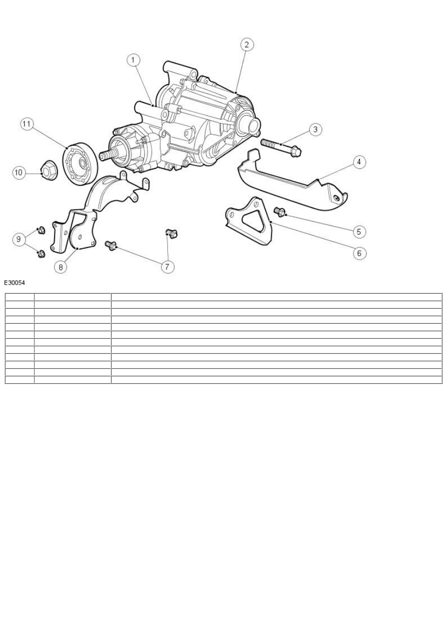
1
—
Transfer case
2
—
Transfer case fill plug
3
—
Transfer case retaining bolt
4
—
Transfer case air cooling duct
5
—
Transfer case Y bracket retaining bolt
6
—
Transfer case Y bracket
7
—
Engine anti-roll restrictor mounting bracket retaining bolts
8
—
Engine anti-roll restrictor mounting bracket
9
—
Engine anti-roll restrictor mounting bracket retaining nuts
10
—
Companion flange retaining nut
11
—
Companion flange
The transfer case system consists of a power transfer unit, rear driveshaft, coupling device and rear axle. The power transfer unit is a
gearbox that attaches to the transaxle. The right hand halfshaft engages to the transfer case link shaft which engages to the differential
side gears as in a normal 4x2 application. The transfer case provides power to the driveshaft through a helical gear spline coupled to the
transaxle differential case, a helical gear drop (idler gear) and hypoid/helical ring gear assembly and pinion set. Repair of the transfer case
is limited to seals and gaskets. If any of the geared components, tappered roller bearings, case cover or internal shafts fail, a new transfer
case must be installed. The transfer case is sealed from the transaxle and has its own sump. The transfer case uses SAE 75W140 synthetic
gear lubricant. The fill plug is located on the top of the transfer case, under the engine anti roll restrictor mounting bracket.