Jaguar X-Type Sedan and Estate (Wagon). Manual - part 373
Item
Part Number
Description
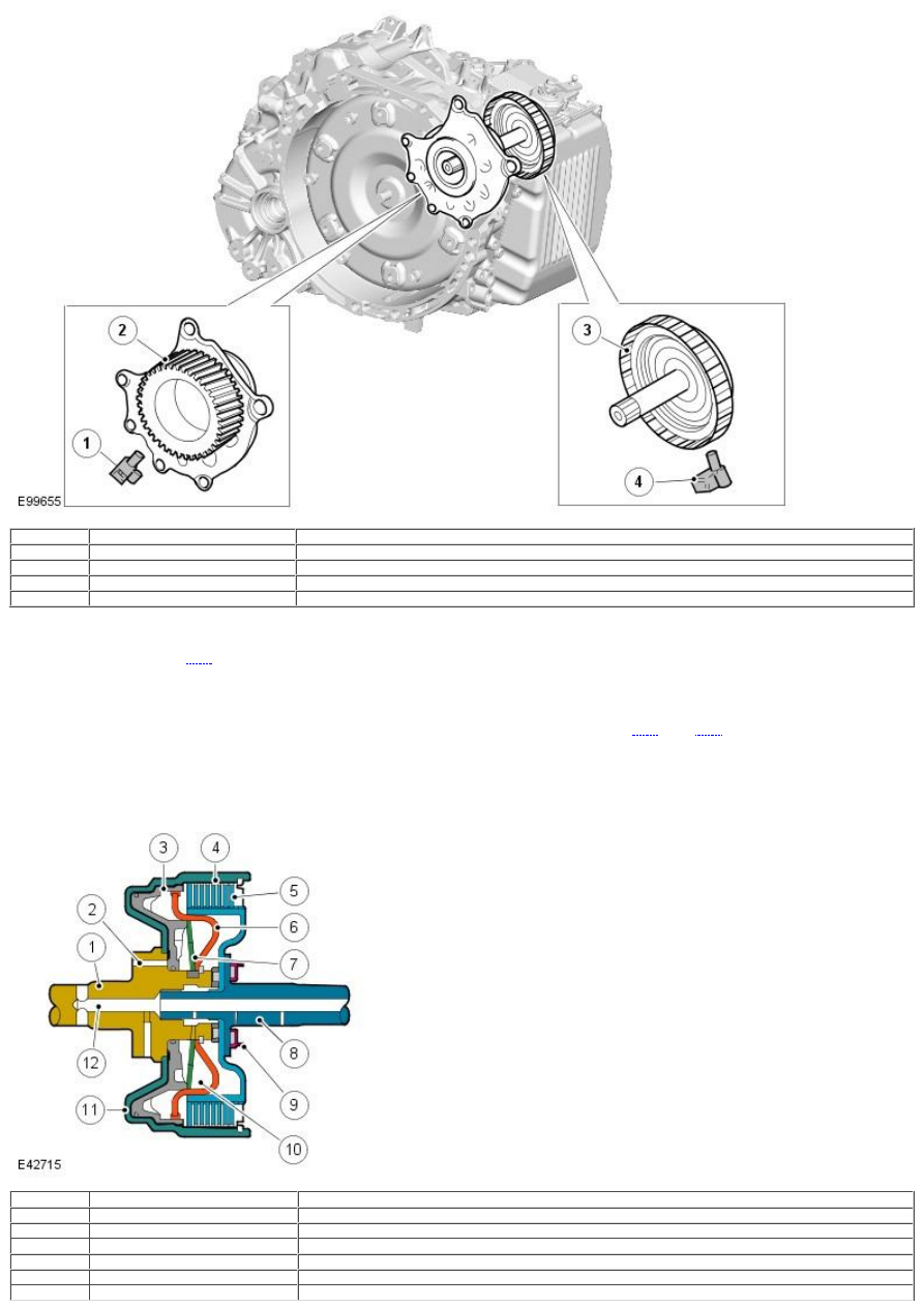
1
-
Speed Sensor (SP) - Output shaft speed
2
-
Counter drive gear
3
-
C2 clutch drum
4
-
Speed sensor (NIN)
Two speed sensors (NIN and SP) are used in the transmission and are located within the transmission housing. Speed sensor (SP) is located
adjacent to the counter drive gear and reads from the gear teeth to provide an output shaft speed signal. Speed sensor (NIN) is located
adjacent to the clutch C" drum and reads off teeth on the outer circumference of the drum to provide an input shaft speed. Both speed
signals are received by the
TCM
which uses the 2 signals to calculate engine torque output, shift timing and torque converter lock-up.
Fluid Temperature Sensor
The fluid temperature sensor is integrated into the internal wiring harness within the transmission. It detects the fluid temperature in the
hydraulic pressure control circuit and transmits a signal corresponding to the temperature to the
TCM
. The
TCM
monitors the temperature
and provides smooth gear shifts across a wide range of temperatures.
DRIVE CLUTCHES
Multiplate Drive or Brake Clutch – Typical
Item
Part Number
Description
1
-
Input shaft
2
-
Main pressure supply port
3
-
Piston
4
-
Cylinder – External plate carrier
5
-
Clutch plate assembly
6
-
Baffle plate