Jaguar X-Type Sedan and Estate (Wagon). Manual - part 262
Published: 11-May-2011
Fuel Charging and Controls - 2.0L NA V6 - AJV6/2.5L NA V6 - AJV6/3.0L NA V6 - AJ27
- Fuel Charging and Controls2.5L NA V6 - AJV6/3.0L NA V6 - AJ27, VIN Range:
J28493->V99999
Diagnosis and Testing
1. Verify the customer concern by operating the system.
1.
2. Visually inspect for obvious signs of mechanical or electrical damage.
2.
3. If an obvious cause for an observed or reported concern is found, correct the cause (if possible) before proceeding to the next
step.
3.
4. If the concern is not visually evident, use a fault code reader to retrieve fault codes before proceeding to the Symptom Chart.
4.
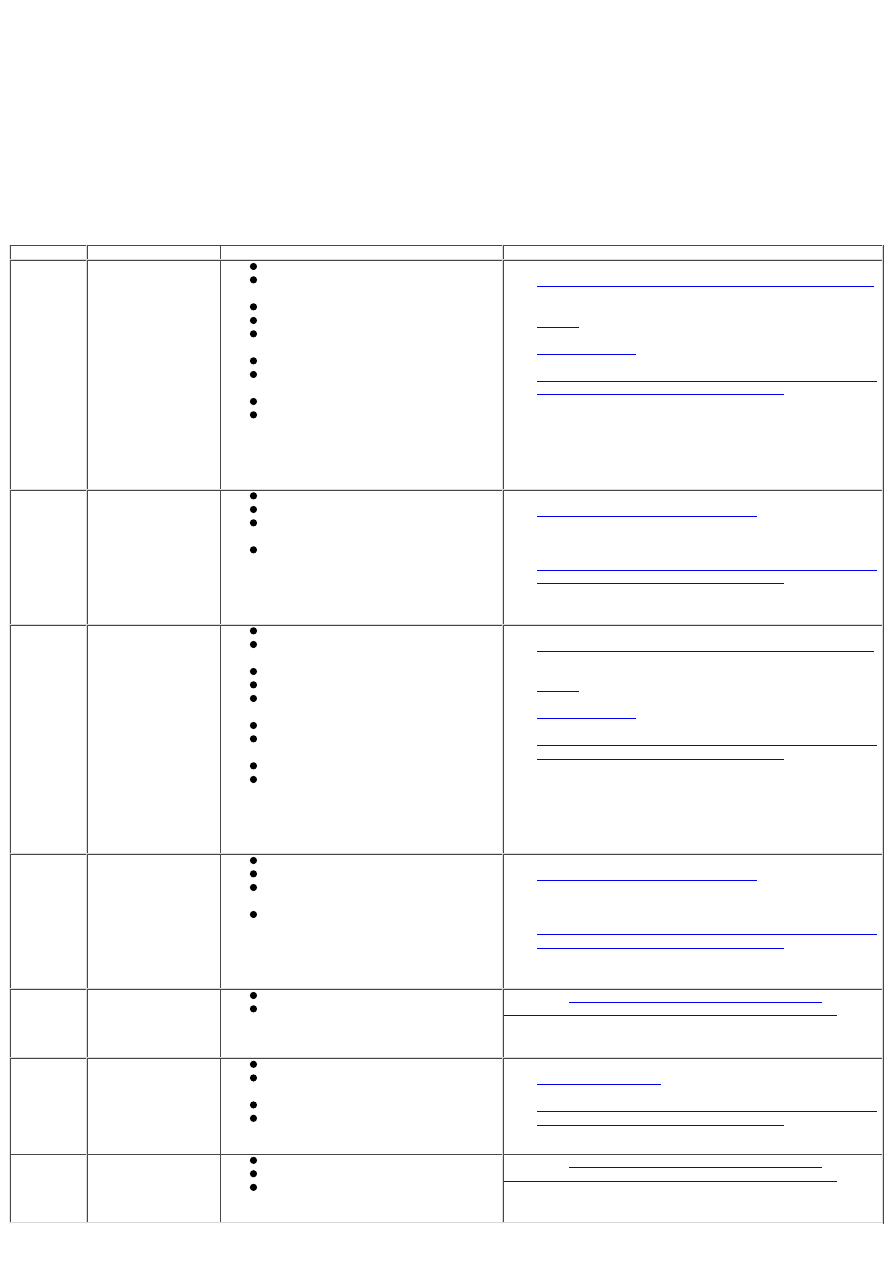
Symptom Chart
DTC
Condition
Possible Causes
Action
P0171
Right-hand bank
combustion too lean
Engine misfire
Air intake leak between MAF sensor
and throttle
Fuel injector restriction
Fuel filter/system restriction
fuel pulse damper failure (low fuel
pressure)
Low fuel pump output
HO2S (1/1; ½) harness wiring
condition fault
Exhaust leak (before catalyst)
engine control module (ECM)
receiving incorrect signal from one or
more of the following components;
ECT sensor, MAF sensor, IAT sensor,
IP sensor, EFT sensor, TP sensor
REFER to:
Engine Ignition - 2.5L NA V6 - AJV6/3.0L NA V6 - AJ27
(303-07A Engine Ignition - 2.0L NA V6 - AJV6/2.5L NA
V6 - AJV6/3.0L NA V6 - AJ27, Diagnosis and Testing),
Engine
(303-01A Engine - 2.0L NA V6 - AJV6/2.5L NA
V6 - AJV6/3.0L NA V6 - AJ27, Diagnosis and Testing),
Exhaust System
(309-00 Exhaust System, Diagnosis
and Testing),
Electronic Engine Controls - 2.5L NA V6 - AJV6/3.0L NA
V6 - AJ27, VIN Range: J28493->V99999
(303-14A
Electronic Engine Controls - 2.0L NA V6 - AJV6/2.5L NA
V6 - AJV6/3.0L NA V6 - AJ27, Diagnosis and Testing).
P0172
Right-hand bank
combustion too rich
Restricted air filter
Leaking fuel injector(s)
fuel pulse damper failure (high fuel
pressure)
ECM receiving incorrect signal from
one or more of the following
components; ECT sensor, MAF sensor,
IAT sensor, IP sensor, EFT sensor, TP
sensor
REFER to:
Intake Air Distribution and Filtering
(303-12A Intake
Air Distribution and Filtering - 2.0L NA V6 - AJV6/2.5L
NA V6 - AJV6/3.0L NA V6 - AJ27, Diagnosis and
Testing),
Electronic Engine Controls - 2.5L NA V6 - AJV6/3.0L NA
V6 - AJ27, VIN Range: J28493->V99999
(303-14A
Electronic Engine Controls - 2.0L NA V6 - AJV6/2.5L NA
V6 - AJV6/3.0L NA V6 - AJ27, Diagnosis and Testing).
P0174
Left-hand bank
combustion too lean
Engine misfire
Air intake leak between MAF sensor
and throttle
Fuel injector restriction
Fuel filter/system restriction
fuel pulse damper failure (low fuel
pressure)
Low fuel pump output
HO2S (2/1; 2/2) harness wiring
condition fault
Exhaust leak (before catalyst)
ECM receiving incorrect signal from
one or more of the following
components; ECT sensor, MAF sensor,
IAT sensor, IP sensor, EFT sensor, TP
sensor
REFER to:
Engine Ignition - 2.5L NA V6 - AJV6/3.0L NA V6 - AJ27
(303-07A Engine Ignition - 2.0L NA V6 - AJV6/2.5L NA
V6 - AJV6/3.0L NA V6 - AJ27, Diagnosis and Testing),
Engine
(303-01A Engine - 2.0L NA V6 - AJV6/2.5L NA
V6 - AJV6/3.0L NA V6 - AJ27, Diagnosis and Testing),
Exhaust System
(309-00 Exhaust System, Diagnosis
and Testing),
Electronic Engine Controls - 2.5L NA V6 - AJV6/3.0L NA
V6 - AJ27, VIN Range: J28493->V99999
(303-14A
Electronic Engine Controls - 2.0L NA V6 - AJV6/2.5L NA
V6 - AJV6/3.0L NA V6 - AJ27, Diagnosis and Testing).
P0175
Left-hand bank
combustion too rich
Restricted air filter
Leaking fuel injector(s)
fuel pulse damper failure (high fuel
pressure)
ECM receiving incorrect signal from
one or more of the following
components; ECT sensor, MAF sensor,
IAT sensor, IP sensor, EFT sensor, TP
sensor
REFER to:
Intake Air Distribution and Filtering
(303-12A Intake
Air Distribution and Filtering - 2.0L NA V6 - AJV6/2.5L
NA V6 - AJV6/3.0L NA V6 - AJ27, Diagnosis and
Testing),
Electronic Engine Controls - 2.5L NA V6 - AJV6/3.0L NA
V6 - AJ27, VIN Range: J28493->V99999
(303-14A
Electronic Engine Controls - 2.0L NA V6 - AJV6/2.5L NA
V6 - AJV6/3.0L NA V6 - AJ27, Diagnosis and Testing).
P1251,
P1631,
P1657,
P1658
Concern with throttle
motor relay
Throttle motor relay
Throttle motor relay circuit
REFER to:
Electronic Engine Controls - 2.5L NA V6 -
AJV6/3.0L NA V6 - AJ27, VIN Range: J28493->V99999
(303-14A Electronic Engine Controls - 2.0L NA V6 -
AJV6/2.5L NA V6 - AJV6/3.0L NA V6 - AJ27, Diagnosis and
Testing).
P0112,
P0113
Concern with IAT
sensor
Engine faulty leading to overheating
Intake air temperature (IAT) sensor
fault
Harness fault
ECM failure
REFER to:
Acceleration Control
(310-02 Acceleration Control,
Diagnosis and Testing),
Electronic Engine Controls - 2.5L NA V6 - AJV6/3.0L NA
V6 - AJ27, VIN Range: J28493->V99999
(303-14A
Electronic Engine Controls - 2.0L NA V6 - AJV6/2.5L NA
V6 - AJV6/3.0L NA V6 - AJ27, Diagnosis and Testing).
P0121,
P0122,
P0123,
P0222,
P0223
Concern with throttle
position (TP) sensor
TP sensor fault
Harness fault
ECM failure
REFER to:
Electronic Engine Controls - 2.5L NA V6 -
AJV6/3.0L NA V6 - AJ27, VIN Range: J28493->V99999
(303-14A Electronic Engine Controls - 2.0L NA V6 -
AJV6/2.5L NA V6 - AJV6/3.0L NA V6 - AJ27, Diagnosis and
Testing).