Jaguar X-Type Sedan and Estate (Wagon). Manual - part 116


  Index      Jaguar     Jaguar X-Type Sedan and Estate (Wagon) (2.0 L, 2.5 L and 3.0 L Gasoline; 2.0 L and 2.2 L, Diesel) - manual 2001-2009 year


Search            


Content   ..  114  115  116  117   ..


Jaguar X-Type Sedan and Estate (Wagon). Manual - part 116


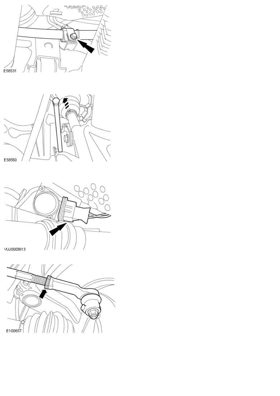
20. Attach the power steering high pressure pipe.

Vehicles with high intensity discharge headlamps

21. Attach the link rod to the headlamp leveling sensor.

All vehicles

22. Connect the power steering control valve actuator electrical connector

(if equipped).

23. NOTE: Right-hand shown, left-hand similar.

Connect tie-rod end ball joints.

1. Attach both tie rod ends to previously noted positions.

2. Tighten tie rod locking nut.

Right-hand drive vehicles

24. Install the right-hand wheel arch liner access cover.

All vehicles

25. Carry out steering system bleed procedure.

For additional information, refer to: 

Power Steering System Filling

(211-00 Steering System - General Information, General Procedures).

26. 

CAUTION: Make sure the steering column coupling is installed

with the vehicle on its wheels. Failure to follow this instruction may result
in damage to the vehicle.

Install the steering column coupling.
For additional information, refer to: 

Steering Column Coupling

 (211-04

Steering Column, Removal and Installation).

27. NOTE: If the steering gear is being replaced for leakage or noise
related issues and there is no evidence of fluid contamination, there is no
need to replace the reservoir.

In some cases where the fluid clearly contains particulate matter, and
the system continues to function, flush the system with fresh fluid and
replace the reservoir, as there is the possibility that the reservoir
internal filter may be damaged or faulty.

28. Using the Jaguar approved diagnostic system, configure the steering

angle sensor.

Published: 11-May-2011

Steering Linkage -

Torque Specifications

Description

Nm

lb-ft

lb-in

Tie-rod end retaining nut

35

26

-

Tie-rod end lock nut

40

30

-

W heel nuts - Vehicles with steel wheels

80

59

-

W heel nuts - Vehicles with aluminium wheels

103

76

-

Published: 11-May-2011

Steering Linkage - Steering Linkage

Description and Operation

Item

Part Number

Description

1

Steering gear

2

Tie-rod end boot

3

Tie-rod

4

Tie-rod end

5

W heel hub assembly

6

Tie-rod end retaining nut

7

Tie-rod end lock nut

The left and right-hand tie-rod assemblies:

Transmit steering forces from the steering gear to the wheel hubs.
Provide front road wheel toe setting by adjustment of the threaded outer tie-rod ends.

• NOTE: Steering geometry adjustments must only be carried out with the vehicle on turn plates to allow the wheels to move during
adjustment.

The left and right-hand steering rack boots:

Are installed between the steering rack and the tie-rod ends.
Are of the concertina type.
Retain lubricant and prevent the ingress of foreign matter.


Content   ..  114  115  116  117   ..