Jaguar XJ-S. Manual - part 150
595
1/2
1
1
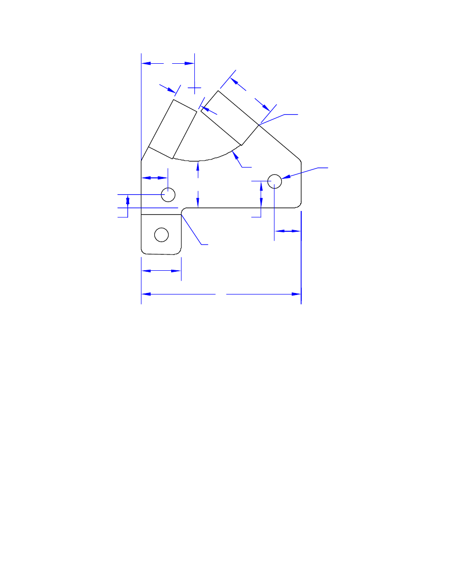
FOLD
UP 90°
1/2
1/2
1/2
3/4
7/8
FOLD
DOWN 90°
R 1-3/8
ø1/4
3 PL
3
1/4
Figure 29 - Bracket for Mitsubishi Reservoir
If the MicroSoft gods are smiling down on us today, Figure 29 will print in actual size. So, just load a piece of sheet
metal into the ol’ inkjet and let ‘er rip!
The bottom of the reservoir should be flush with the top of the existing support bracket, but the hose clamp will need to
go around the reservoir about 1/2” up from the bottom; hence the two “legs” on this bracket being 1” tall. There is even
a little ridge on the Mitsubishi reservoir -- it’s actually the “MIN” level line -- that will neatly sit on top of one of these
legs so it cannot slide downward.
The asymmetric design of this bracket serves to mount the Mitsubishi reservoir about 1/2” closer to the power brake
booster than the original reservoir was. This provides more clearance to the throttle cable, as well as making it a bit
easier to wrap your hand around the cap when unscrewing it.
The bent-down tab at the lower left in the diagram is simply to provide a place to fasten the wire connector down. If
you wish, you can omit this tab and just slice the bracket straight across the bottom edge, and provide other means of
fastening down the connector -- or just let it dangle. A generic strip of steel with 1/4” holes can be used by merely
bending it 90° in the middle and mounting it under the same mounting bolt that holds the reservoir bracket itself.
The design shown above is for a LHD car. Those with RHD cars will probably need to make a mirror image of this
bracket -- which means cut out the exact same piece, but bend the two mounting tabs down instead of up and the wire
connector tab up instead of down.
The hose fittings on the Mitsubishi reservoir are 10mm, while the fittings on the Jag master cylinder are 1/4”. You will
need to devise a way to connect these sizes up. A 3/8” air hose will fit the Mitsubishi reservoir just fine. The simplest
idea is to use two different sizes of hose with an adapter in between.