Jaguar XJ-S. Manual - part 13


  Index      Jaguar     Jaguar XJ-S - service repair manual 2006 year


Search            


Content   ..  11  12  13  14   ..


Jaguar XJ-S. Manual - part 13


47

Jim Isbell didn’t like how much grief was required getting the plug out after it had dried up, and determined it wouldn’t 
happen again.  “I have cut the tabs off of the rubber plug that fills the adjustment hole for the chain tensioner.  I have 
made a simple aluminum “L” shaped piece that fits under a water pump bolt and holds the plug so it won't fall out.”  

If desired, the opening may be plugged with a compressible rubber type freeze plug.  This may even be preferable to the 
original plug, since it will make a reliable airtight seal.  Be sure that the plug does not interfere with the timing chain or 
the operation of the tensioner. 

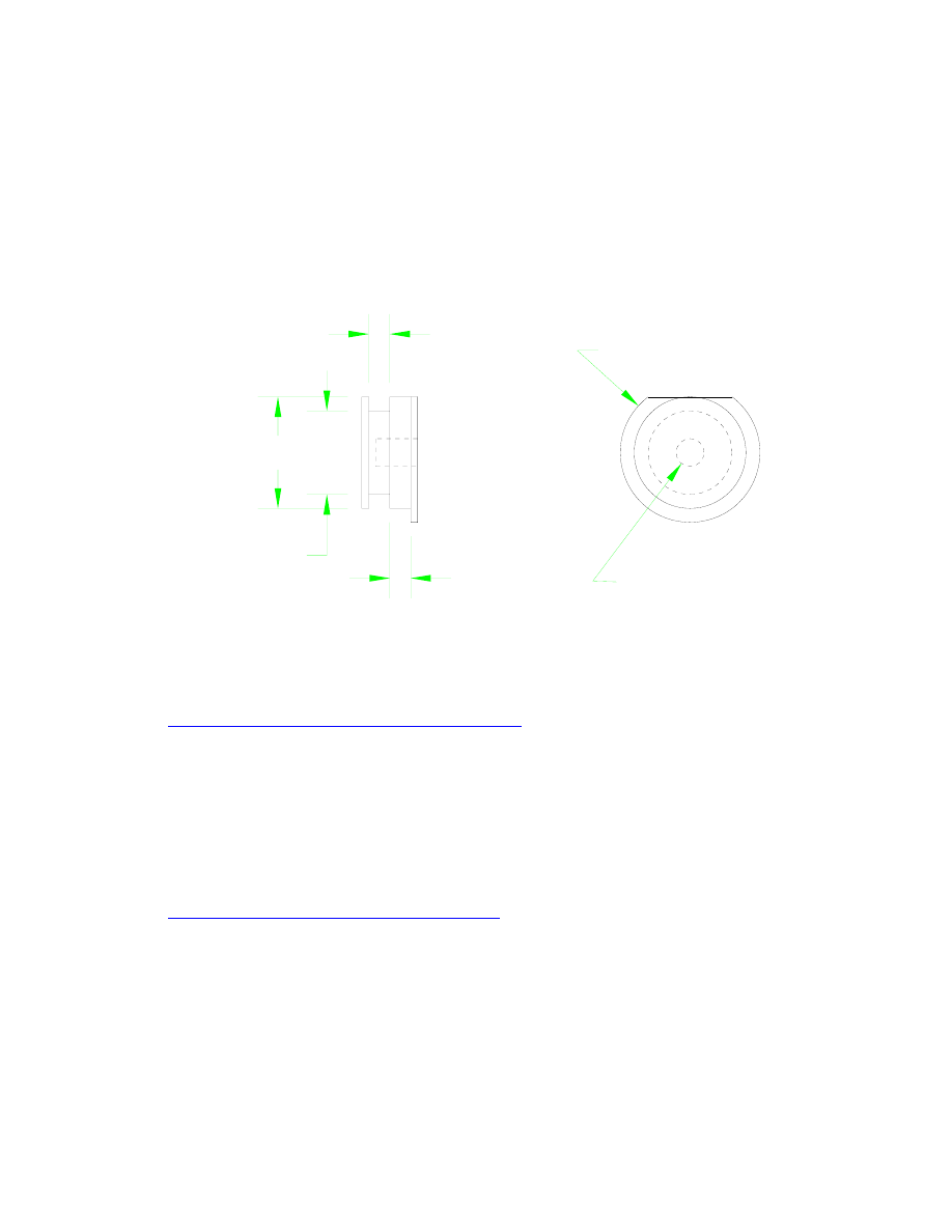
It isn’t too difficult to make an aluminum plug for this hole with provision for fitting an O-ring for sealing.  Figure 2 
shows a design. 


8125" dia

.990" dia

1/4"-20

3/16"

3/16"

1-1/4" dia


Figure 2 - Timing Chain Tensioner Access Hole Plug 

One such plug was machined by Ron Morse and successfully tested on the author’s car; you can see a picture of this 
installation at 


http://www.jag-lovers.org/xj-s/book/TensionerPlug.html


Note that, even though this plug fits snugly in the hole when fitted with a proper Viton O-ring (#210), it lacks any 
positive retention and therefore might blow out if pressure builds in the crankcase for some reason.  Since you don’t 
want to lose it after paying to have it made, something similar to Isbell’s little tab under a water pump bolt is in order to 
make sure it stays put.  The threaded hole in the center is to aid in removal when you actually want to get it out; just 
screw in a 1/4” screw and use it to pull or pry on. 

If you don’t want to make your own, Ron Kelnhofer (page 716) has some for sale.  His are very similar to the 
illustration shown except that he has added a retention scheme, a checkball that can be engaged to grip the side of the 
opening so a separate tab under a bolt head is not necessary.  You can see a picture of his plug at 


http://neptune.spacebears.com/cars/engr/tension.html


OIL LEAKS AT SANDWICH PLATE BOLTS:  The bolts that hold the sandwich plate to the bottom of the block are 
threaded into holes that open at the top to the outside of the block; if you used bolts that were too long, the ends of the 
bolts would stick up through the flange and be visible from outside the engine.  This arrangement was no problem with 
the oil pan used on the SIII E-Type, since the bolt heads were likewise visible from outside the engine and the gasket 
would seal between the pan and the block inboard of the bolt holes, so the bolts themselves would remain dry.  When 
the sandwich plate configuration was introduced in the XJ12 and XJ-S, however, a widened oil pan was provided at the 


48

rear end of the engine and the heads of some of the bolts holding the sandwich plate to the block are completely 
enclosed within the pan.  These same bolts also hold a baffle tray in place, but since everything is inside the crankcase, 
no gaskets are used. 

The result is that oil can seep into the space surrounding the bolts and then upward through the threads and come out on 
the outside of the block.  Not good.  If the sandwich plate had been introduced with the V12 at the outset, they probably 
would have made the holes in the block “blind holes” so oil couldn’t leak through; this was done in several other 
places, as though someone was thinking about it at the time. 

Jaguar apparently figured out the problem -- in 1994.  That’s the date of Technical Service Bulletin 12-53, which 
describes a simple fix:  Drain the oil, remove the oil pan, remove the guilty bolts, clean the oil off the bolts and out of 
the threaded holes, apply a thread sealant to the bolt threads, and reassemble.  This is a snap, and well within the 
capabilities of anyone capable of changing their own oil -- and is convenient to do during an oil change, and won’t even 
add much time to the job. 

The TSB specifies that “Loctite Primer” be applied to the hole threads.  Apparently Loctite primers are essentially 
acetone- or hepatone-based cleaners.  You can use plain acetone on a swab to clean the threads well enough for a thread 
sealant to work. 

For sealing, the TSB specifies that  Loctite 545 be applied to the bolt threads.  Note that 545 would mean a sealant, not 
to be confused with Loctite 600-series products that are threadlockers.  Earl Huff found that Loctite 545 was an 
industrial product not generally available to the home mechanic, so he called Loctite for advice:  “After learning what I 
intended to use the stuff for, the very helpful fellow I spoke with said that Permatex silicone RTV sealant or even the #2 
sealant would probably work just as well.”  This author used #2 for this job and it worked well. 

The TSB indicates that there are 9 bolts involved on the XJ-S but only 7 bolts on the XJ12.  It’s unknown where they 
got these numbers or why they would be different; on this author’s ’83, there are 8 bolts that required sealing. 

The TSB mentions that the bolts and gasket involved were upgraded after engine 8S 86317 (or 8W 10641 on XJR-S 
cars), so if your engine is earlier than these numbers you’re supposed to replace the bolts and use the newer style gasket 
EBC 9623 when reassembling. 

It’s probably not the same bolts that need upgrading and sealing.  There are two types of bolts on and within the oil pan 
on a pre-metric engine (pre- 8S24175):  5/16”-18 Grade 5 bolts 1-3/4” long with spiral groove washers that go through 
the sandwich plate into the block, and 5/16”-18 washer-faced bolts 3/4” long that thread into the sandwich plate itself.  
The bolts that need sealing are the 1-3/4” ones with heads within the sump.  The 3/4” screws have the dreaded 
triangulated threads that strip out holes in aluminum, so these bolts were probably the subject of that upgrade. 

Chances are good that the bolt upgrades are similiar to that for the cam cover (see page 59), so using the same strategies 
for non-Jaguar bolts described there would probably work here as well.  You’ll need nineteen 5/16”-18 bolts 3/4” long. 
 Grade 5 hex head bolts would work well, Grade 8 even better.  Since you probably won’t have washer-faced heads, 
you’ll need washers as well -- the 8mm spring washers described on page 26 will work nicely. 

Although it’s probably not necessary, you could also replace the 1-3/4” Grade 5 bolts with Grade 8’s.  You’ll need 
fifteen.  Finding 1-3/4” Grade 8 bolts is not always easy, so let me make it easier for you: get 2” bolts instead.  They fit 
better.  You can reuse the spiral groove washers. 

Of course, you might also consider replacing all the bolts you can get to on the front half of the sandwich plate that 
aren’t associated with the oil pan.  On a pre-metric engine these are 5/16”-18 bolts 1” long and there are eighteen of 
them, but you probably won’t want to try to get to four that are above the crossmember for the front subframe. 

On metric engines, all of these bolts are probably 8mm instead of 5/16” and the lengths are multiples of 5mm.  It’s 
probably the same number of bolts of each length, though.  Remember that metric class 8.8 is roughly equal to Grade 5 
and metric class 10.9 is roughly equal to Grade 8. 

When sealing and/or replacing bolts that hold the sandwich plate to the block, it’d be a good idea to do one at a time 
since you don’t want to disturb the upper gasket. 


49

SANDWICH PLATE GASKETS:  If you’re doing the job described above to seal the sandwich plate bolts, it makes 
sense to buy just the lower gasket.  If you’re addressing gasket leaks, one could argue that replacing the lower without 
replacing the upper is a waste of time.  Of course, replacing the lower with the engine in the car is easy, replacing the 
upper is not.  You could argue that replacing just the lower is worth a try, and if it doesn’t work you can go back and do 
them both and buy a second lower gasket. 

When you have the stamped sheet steel pan off, set it down right side up and clean up the flat upper surface.  Inspect 
the holes closely.  If they seem to be dished upward a bit from the bolt tension, set the ball end of a ball pein hammer in 
the hole and whack it with another hammer.  The metal around the hole should end up slightly dished downward.  
When you tighten the bolts down the area will be pulled back flat, but compression will be applied more uniformly over 
the area of the gasket. 

As a point of information:  Jaguar didn’t provide a sandwich plate between block and oil pan just to maximize leakage. 
 The sandwich plate is structural; bolting it to the block makes the block assembly more rigid.  Rigidity is very 
important; when an engine operates at high power, the pulses at alternating cylinders can cause the block to twist and 
flex.  This can misalign the main bearings holding the crank and cause them to get wiped out.  When a block is thick 
cast iron it might be rigid enough for everyday use, but when you’re designing a long V12 block made of aluminum 
and intended for high performance work, you need to do what you can to maximize structural rigidity. 

Craig Sawyers provides actual specs:  

Torsional stiffness in lbft/degree 
Bare block: 5445 
Block with cylinder liners and sump: 40,830 
Heads, block and sump: 111,700 

“Now admittedly this was the original Series III E-Type engine, in which the sump was a large and deep aluminium 
casting.  However, I believe that the general principle still holds: the sandwich plate is indeed structural.” 

Unfortunately, Jaguar may have dropped the ball here.  If the sandwich plate is structural, the joint between block and 
sandwich plate needs to transmit shear loads.  It should therefore have close-fitting dowels, probably a half dozen, to 
unite the block with the sandwich plate structurally.  It doesn’t, however, so only the bolts (which fit too loosely in the 
holes for transmitting shear loads) and the gasket itself hold the two parts united.  The shear loads can be expected to be 
hard on the gasket, and putting a thick cork gasket in here in place of the thin OEM gasket would probably be a serious 
mistake.  Reportedly a Ford engineer once opined that this joint will always be inherently prone to leakage. 


SEALING THE DIPSTICK TUBE:  The dipstick tube just slides into a tube on the crankcase and is held in place by a 
bracket bolted to the top of the head.  It’s not sealed.  Of course, it’d be a nice idea to seal it; the fewer leaks, the better, 
and even if the dipstick itself doesn’t seal perfectly (although it just might -- it is a decent design) it’d be a lot harder for 
oil to find its way all the way to the top of the tube than to leak out right there at the bottom. 

Some ideas for sealing this thing:  You might apply a sealant to the end of the tube before sliding it back in.  Or, you 
might fit a small O-ring around the tube before installing it, and make sure that the bracket arrangement holds the tube 
firmly so it applies a little compression onto the end of the fitting on the crankcase.  Of course, Viton is preferred.  Or, if 
you can get your hands in there, you could slide a piece of hose over the joint and clamp it on both sides of the joint. 


OIL IN AIR INTAKES:  Robert Dingli explains the oil that always seems to collect in the air filter housings and 
around the butterflies:  “What you are noticing is probably a mixture of a small amount of engine oil that has been 
forced out as a vapour from the crankcase by blowby gas which has then condensed within the inlet manifold.  You 
may also get some residual fuel (usually the heavier fractions) leaving an oily film.  This is normal even for new 
engines but will tend to get worse as the engine wears. 

“On engines which have the inlet manifold sloping down from the head, there is usually quite a puddle sitting in the 
plenum.  The first time I noticed this was when one of the vacuum lines became blocked.  It turned out to be the line 
which connects to the underside of the plenum.  I have since re-routed that line and plugged the connection.  Whenever 


50

I remove the plug, a thick deep red oily mess dribbles out.  The red colour is obviously the remnants of petrol (leaded 
petrol in Australia is coloured red) which has run down into the plenum after the engine has been stopped.  The lighter 
fractions tend to evaporate when the engine is next heated. 

“Very occasionally, I have been known to pour a small amount of petrol into the plenum to dissolve the goo and then 
drain from the lowest point.” 


FREEZE PLUGS:  Apparently a US-only misnomer; English-speaking countries reportedly properly call them “core 
plugs”.  Some US parts places call them “expansion plugs”.  Alex Dorne clarifies, “I can tell you that the freeze plugs 
are not meant to rescue the block if the coolant freezes.  Due to the casting process they were necessary to make 
mantling of the block possible.”  Of course, that doesn’t mean they won’t pop out when the coolant freezes!  However, 
in warmer climates the most common failure is rust-through. 

If you need to replace these plugs for whatever reason, you will find several versions available, including simple steel 
or brass cup-shaped plugs and copper or rubber assemblies with a bolt through the center for compressing the plug to 
expand it into the opening.  Dorne:  “Most common material seems to be steel for automotive use but when working in 
the marine business I found out that copper is used on “factory built” marine engines to prevent corrosion problems 
when fresh water cooled. 

Note that the original plugs are concave side out, but replacements are installed the other way.  “Installing the plugs is a 
piece of cake (if the block is out of the vehicle, of course).  Place the plug in its seat, convex side out, hold a ball ended 
hammer in the center of the plug, give it a hit with a second hammer.  This flattens the plug and increases the diameter a 
little bit.  I think it’s a good idea to use some non-hardening sealant on the seat before placing the plug.” 

If the cupped plug is a little too tight to install, it is a simple matter to make it a little smaller.  Set the plug in a large 
socket or box end wrench, put a steel ball (or the head of a ballpien hammer) in the center and hit it with a hammer. 

Since the Jaguar V12 has an open-top deck design, there is little reason for other casting openings and there are no 
plugs on the side of the block.  There is one plug on the rear end of each bank, within the bellhousing.  On the head, 
there are three 7/8” plugs on the exhaust side, four 7/8” plugs on the intake side (visible within the V), and one 1-3/8” 
plug at the back end. 


PCV SYSTEM:  The way a typical PCV system works is pretty simple:  A scheme is provided that draws fresh air into 
one side of the crankcase and out the other side and into the engine intake.  This serves at least three purposes:  First 
(and foremost to emissions regulators) it prevents the vapors gathering in the crankcase from escaping into the 
atmosphere.  Second, it provides fresh air inside the crankcase rather than yucky fumes, some of which may be 
corrosive or explosive.  Third, the suction causes a slight vacuum within the crankcase, which causes leaks to leak air in 
rather than oil out.  For these benefits, there are essentially zero disadvantages other than the minimal cost of the 
components.  There once was a concern about effects on fuel mixture, but when carburetors were superceded by EFI 
that concern evaporated. 

Dave Osborne says you can learn more about typical PCV systems at: 


http://www.filtercouncil.org/techdata/tsbs/94-2R.html


Unfortunately, this all describes a typical PCV system -- not the one in the Jag.  Rather than the flow-through scheme of 
a typical system, the V12 has only one opening into the crankcase.  This vent is connected to a chamber built into the 
LH air filter housing.  The chamber has a fairly large opening into the air filter housing itself.  The PCV valve is also 
connected to this chamber.  Flow-through ventilation of the crankcase is clearly not possible.  It’s doubtful such a 
system will apply a significant vacuum to the crankcase, other than when the LH air filter is plugged up.  The only 
objective it will achieve is pollution control; vapors cannot escape the crankcase without going either into the air intake 
or into the inlet manifold. 


Content   ..  11  12  13  14   ..