Jaguar XJ (X350). Manual - part 789


  Index      Jaguar     Jaguar XJ (X350) - service repair manual 2003-2009 year


Search            


Content   ..  787  788  789  790   ..


Jaguar XJ (X350). Manual - part 789


Exhaust Gas Re-Circulation 
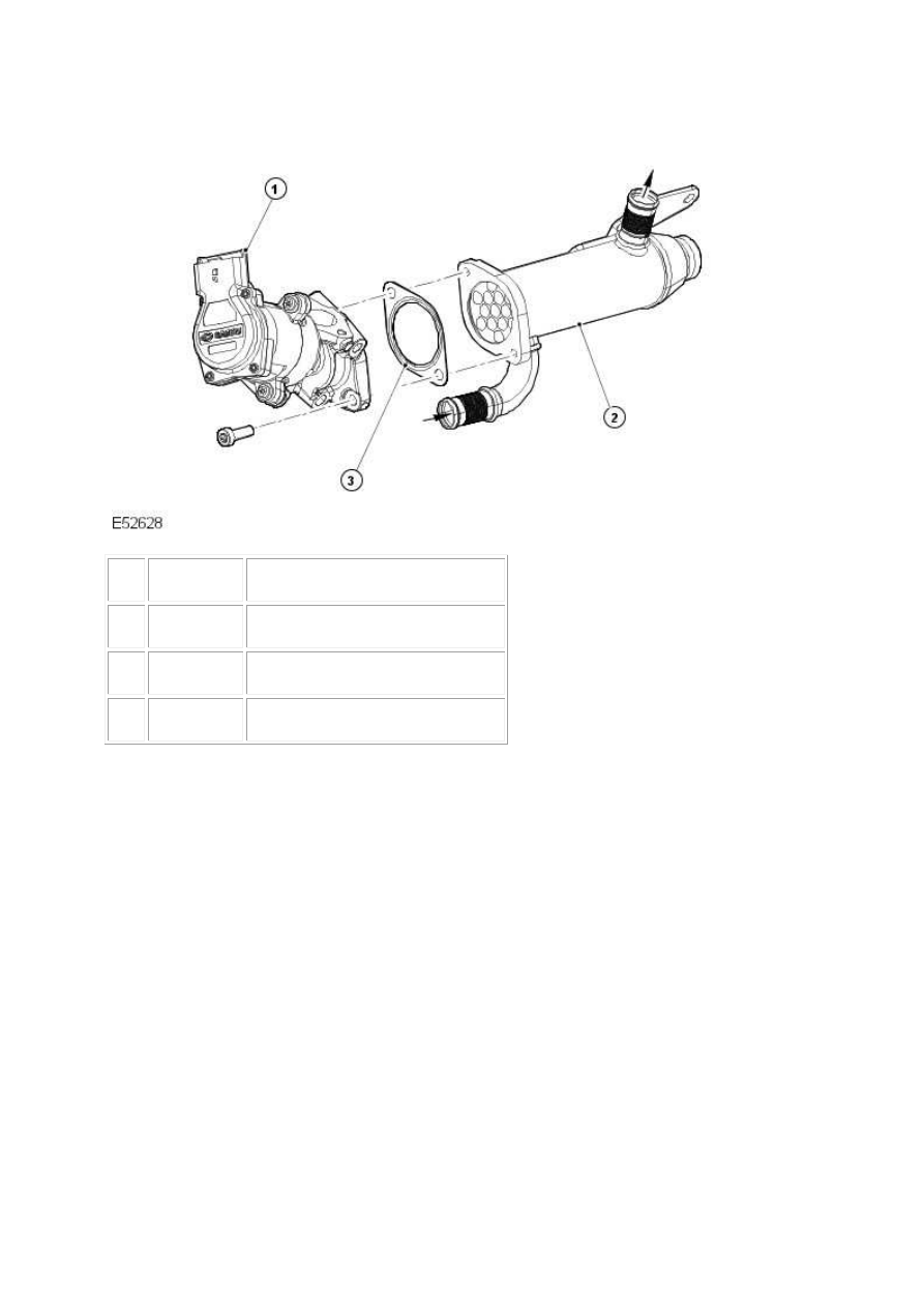
 

Item


Part Number


Description


1


Exhaust gas recirculation (EGR) valve


2


EGR cooler 


3


Gasket


The exhaust gas re-circulation (EGR) system is fitted to the engine in order to reduce the amount of 

nitrogen oxide (NOx). This is done by reducing the temperature of the combustion process by 

introducing some waste exhaust gases into the inlet manifold. The effect of this is that there is a 

depletion of oxygen which reduces the temperature of the combustion process and in turn reduces 

the amount of NOx produced. 


The engine control module (ECM) will determine the amount of EGR operation depending on the 

engine rpm, intake air temperature, coolant temperature and fuel flow rate. The amount of exhaust 

gas being recirculated is measured by a combination of position sensing of the valves and a mass air 

flow (MAF) sensor. 


The EGR valves are operated through their full range at each engine start-up. This is to clear any 

carbon deposits that may have built up whilst the engine was running. 


The EGR system is continually monitored for faults. Depending on how the system fails, the ECM will 

dictate whether the malfunction indication light (MIL) is on or off. In the event of a failure of the EGR 

system, the ECM will use substitute values and the EGR function will become inoperative. 


The EGR cooler is connected to the vehicle cooling system via hoses and is there to cool the exhaust 

gases being recirculated. 


The EGR valve and cooler are supplied as separate components. The EGR valve itself should not be 

disassembled. 


www.

Diagnosis and testing


Engine Emission Control   

Principle of operation 

Exhaust gas recirculation (EGR) 

The EGR system recycles exhaust gases back through the combustion process to reduce NOx 

emissions. 


By introducing this gas into the air intake, oxygen content and combustion temperatures are 

reduced, which reduces the NOx emissions. 


High EGR flow is necessary during cruising and mid-range acceleration, when combustion 

temperatures are typically very high, while lower EGR flow is needed during low speed and light load 

conditions. 


No EGR flow should occur during conditions when it could adversely affect engine operating 

efficiency or vehicle driveability, such as engine warm-up, idle, etc. 


The EGR function of the 2.7 L engine is managed by the engine control module (ECM), which controls 

the operation of stepper motors, allowing precise control of the EGR valve actuators. 


The ECM determines the optimum EGR flow using inputs from sensors in the engine management 

system, including the mass air flow meters, coolant temperature sensor, and intake air temperature 

sensor. 

Positive crankcase ventilation 

The crankcase ventilation system uses the depression created in the air intake to draw vapors from 

the crankcase through the engine where they are burnt with the fuel/air charge. 


By doing this, any build-up of pressure inside the crankcase is avoided, reducing blow-by and 

potential oil leakage problems, while still reducing emissions into the atmosphere. 


The 2.7 L engine crankcase ventilation is through a cyclone separator mounted in the engine 'V'. 


The separator consists of a diaphragm and spring inside the casing which respond to crankcase 

pressure variations and separate the oil from the vapor, allowing the oil back into the engine while 

the vapor is directed to the intake system. 

Overview 

There are changes to the engine management system (EMS) for 2006 my, the most obvious of which 

will be the change to 7-digit diagnostic trouble codes (DTCs) from the familiar 5-digit. 


Refer to the DTC index in this section for guidance on how to use these codes with the Jaguar 

approved diagnostic system or a scan tool. 

Inspection and verification 

1 . Verify the customer concern.  


2 . Visually inspect for obvious signs of mechanical or electrical damage.  

Mechanical 


Electrical 


Engine breather hoses  

Cyclone separator  

EGR Pipes (check for cracks) 

Electrical connections to the stepper motor(s) 

Stepper motor(s)  

Harnesses  

Mass air flow (MAF) sensors  

Manifold absolute pressure (MAP) sensor  

Intake air temperature (IAT) sensor  

Intake air shutoff throttle  

Engine control module (ECM) 


3 . If an obvious cause for an observed or reported concern is found, correct the cause (if possible) 

before proceeding to the next step.  


4 . If the cause is not visually evident use the Jaguar approved diagnostic system or a scan tool to 

retrieve the fault codes before proceeding to the DTC index, or the symptom chart if no DTCs are set.  

Symptom chart 

Symptom 


Possible source 


Action 


Difficult to start 


EGR valve stuck 

open 


Inspect the system (see visual inspection). Check for 

DTCs. 


Poor idle quality 


EGR valve stuck 

open 


Inspect the system (see visual inspection). Check for 

DTCs. 


Lack of power when 

accelerating 


EGR valve stuck 

open 


Inspect the system (see visual inspection). Check for 

DTCs. 


Engine stops/stalls 


EGR valve stuck 

Inspect the system (see visual inspection). Check for 

www.


Content   ..  787  788  789  790   ..