Jaguar XJ (X350). Manual - part 781
 

  Index      Jaguar     Jaguar XJ (X350) - service repair manual 2003-2009 year


Search            


Content   ..  779  780  781  782   ..


Jaguar XJ (X350). Manual - part 781


Exhaust Manifold to Exhaust Gas 
Recirculation (EGR) Valve Tube (17.45.11)   

Removal  

Vehicles with supercharger  


1 

. 


Remove the exhaust gas recirculation (EGR) valve.  

For additional information, refer to Exhaust Manifold to Exhaust Gas Recirculation (EGR) 

Valve Tube (17.45.11)  


Vehicles without supercharger  


2 . Remove the intake manifold.  

For additional information, refer to Intake Manifold - VIN Range: G00442->G45703 (30.15.01)  

For additional information, refer to Intake Manifold - VIN Range: G45704->G99999 (30.15.01)  


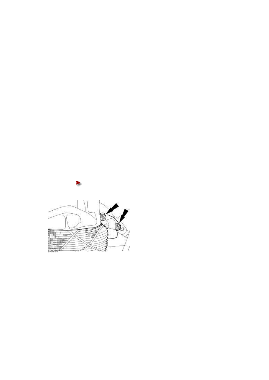
3 . Remove the exhaust manifold to exhaust gas recirculation (EGR) valve tube. 


Remove and discard the gasket.


Installation  

Vehicles with supercharger  


1 . Install the EGR valve.  

For additional information, refer to Exhaust Gas Recirculation (EGR) Valve (17.45.01)  


Vehicles without supercharger  


2 . Install the exhaust manifold to exhaust gas recirculation (EGR) valve tube. 


Install a new gasket.


Tighten to 21 Nm.


3 . Install the intake manifold.  

For additional information, refer to Intake Manifold - VIN Range: G00442->G45703 (30.15.01)  

For additional information, refer to Intake Manifold - VIN Range: G45704->G99999 (30.15.01)  


www.

Secondary Air Injection (AIR) Control 
Valve - 3.0L NA V6 - AJ27   

Removal  


1 

. 


Remove the secondary air injection (AIR) control valve to exhaust manifold right-hand tube.  

For additional information, refer to Secondary Air Injection (AIR) Control Valve to Exhaust 

Manifold Tube RH - 3.0L NA V6 - AJ27  


2 . Disconnect the AIR switching valve electrical connector. 


3 . Disconnect the AIR switching valve vacuum hoses. 


4 . Detach the AIR wiring harness.  


5 . Disconnect the AIR control valve vacuum hose. 


6 . NOTE:  


Note the position of the timing marks on the AIR control valve and the AIR supply hose. 


Disconnect the AIR supply hose.  


7 . Remove the AIR control valve and bracket assembly. 


Installation  


1 . To install, reverse the removal procedure. 


Tighten to 8 Nm.


www.


Content   ..  779  780  781  782   ..