Jaguar XJ (X350). Manual - part 370
tensioner blades, the secondary chain tensioners act directly on the chains.
A woodruff key locates the drive sprocket on the crankshaft and these are retained in position by the
crankshaft damper pulley.
Item
Part Number
Description
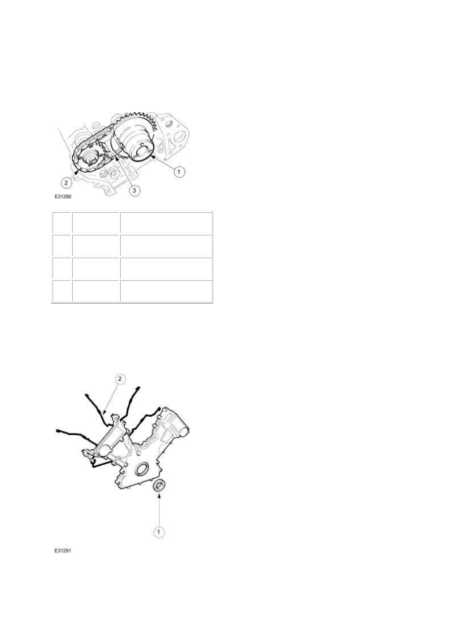
1
—
Variable valve timing unit
2
—
Secondary chain
3
—
Secondary chain tensioner
The variable valve timing (VVT) oil control unit and the exhaust camshaft sprockets are non-
interference. They are clamped in place on the camshafts by the retaining bolt and clamping
plate/washer.
Timing Cover