JAC Light truck HFC1020. Service Manual - part 1
Use of instruments and ap鄄
paratuses in the cab
Integrated switch and instru鄄
ment cluster
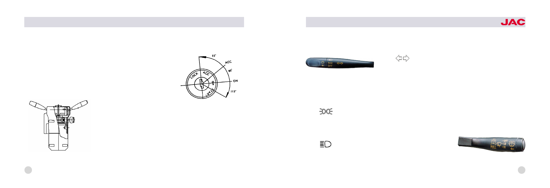
Integrated switch
(figure below)
which is composed of steering shaft
lock seat ignition start lock and com鄄
bination switch lies underneath the
steering wheel.
Ignition switch
Ignition switch is on the right side of
integrated switch. It has four func鄄
tions: LOCK尧ACC尧ON尧START. When
the key is on the 'LOCK' position,
the ignition switch has been connect鄄
ed to the power source and the lock鄄
up of steering gear has been disen鄄
gaged. Turn the key to 'ACC' posi鄄
tion clockwise, the circuit of acces鄄
sories like radio and tape player can
be connected. Turn to the 'ON' posi鄄
tion, and the instrument circuit is con鄄
nected. If keep on turning until to the
'START' position, the engine can be
started. You should unlash the han鄄
dle of the key immediately after the
engine started. And the key can re鄄
turn to the 'ON' position by the ac鄄
tion of spring. The schematic dia鄄
gram of ignition switch is as follows.
Combination switch ( left control han鄄
dle)
Combination switch is under the
control of the multifunction handle,
which lies in the lower left and inferi鄄
or place of the steering wheel. It can
control small light尧headlight尧head鄄
light dimmer and turning to the left or
schematic diagram of integrated switch
schematic diagram of ignition switch
HFC1020
series trucks
2
the right by two different movement
modes. The symbol and function of
the combination switch is as follows:
1. The OFF symbol indicates that
small light and headlight do not light.
(But at this time the high beam can
light if you put up the handle.)
2. The
symbol is the indica鄄
tion of small light. Turn the control
handle clockwise by 30毅 ,and the
front尧rear small lights and the instru鄄
ment light can light.
3. The
symbol is the indica鄄
tion of headlight. Keep on the turning
of the left control handle clockwise
by 30毅 , the front headlight尧the rear
small light and the instrument light
can light.
4. The
symbol is the indica鄄
tion of steering. Forward and back鄄
ward motion of the control handle
can operate the left and right turning
lamp and the turn light indicator in
the instrument panel. Push the con鄄
trol handle forward in the horizontal
direction, the right turning lamp lights
and there has the indication of turn鄄
ing right in the instrument panel. On
the other hand, pull the control han鄄
dle backward, the left turning lamp
lights and there has the indication of
turning left in the instrument panel. If
the control handle is in the middle
position, then there has no indication
of turning.
5. Dimmer of headlight: Lift the left
control handle upwards gently and
do the 'uplift -looseness' motion, it
can control the dimmer function of
the headlight. Uplift the handle once,
high beam headlamp lights; loose
the handle, it goes out. Repeating
the above action can control the
work status of the high beam head鄄
lamp to obtain the purpose of dim鄄
mer function when overtaking or
passing in night.
Combination switch (right control
handle)
right control handle
left control handle
3