Engine JAC HFC4DA1-2C. Manual - part 22
Maintenance manual for sunray hfc4da1-2c china-IV diesel engines
87
2)Working Principle
The signal of vehicle speed sensor provides vehicle speed signal to the ECU, based on which the ECU calculates the
vehicle speed. It’s internally composed of one Hall speed sensor. Please refer to the camshaft position sensor for the
working principle.
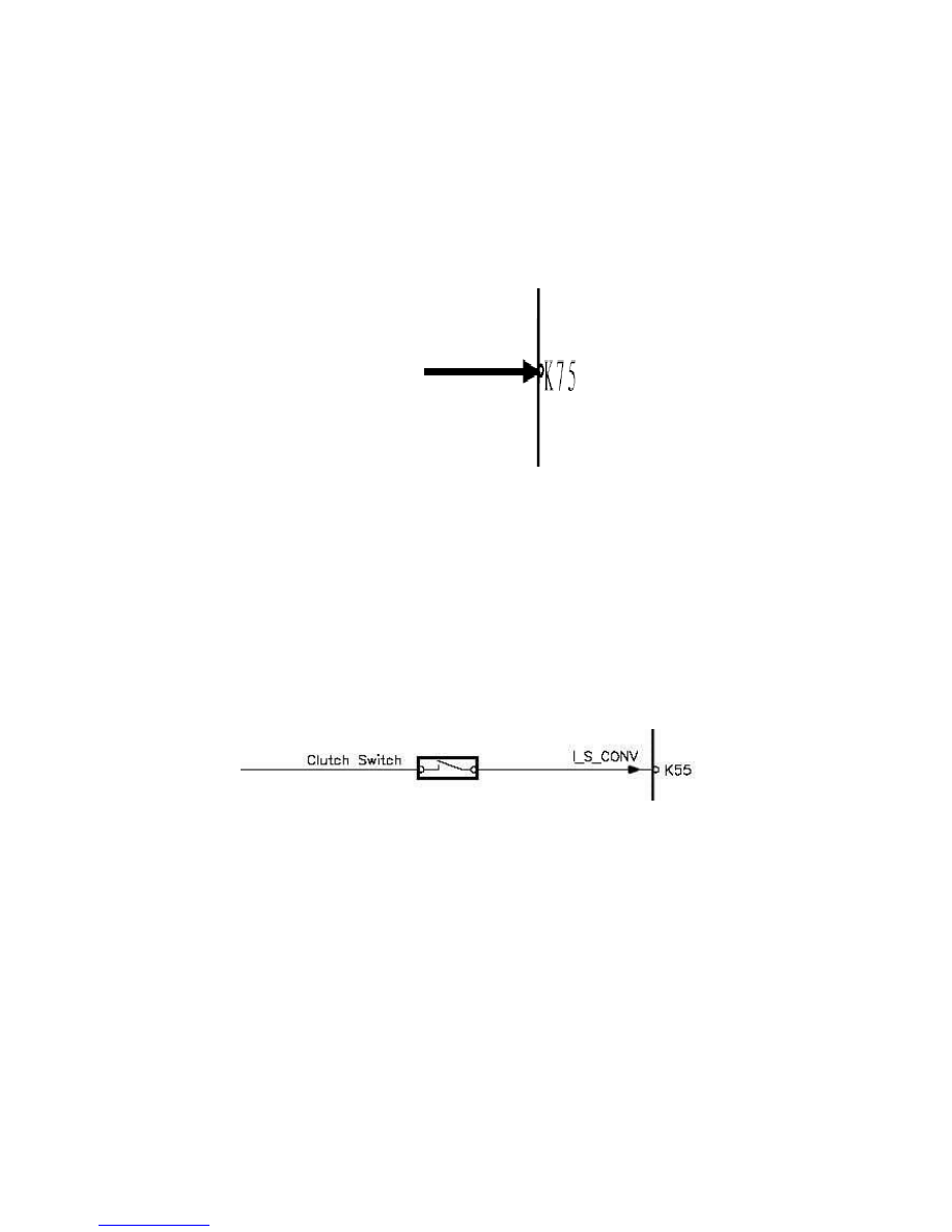
3)Measurement analysis
10. Clutch switch
1) Overview
The clutch switch is located on the upper portion of the clutch pedal and is mainly functioned for cruise control and
engine torque smoothness control.
2) Working Principle
The clutch switch is installed at the clutch pedal and transmits the operation signal of clutch pedal to the engine ECU.
Its inside is one two-pin contact switch. When the clutch pedal is stepped down, the lower central position of the
clutch switch springs out. In such case, two pins of the clutch switch are connected. When the clutch pedal is released,
two pins of the clutch switch are disconnected. Therefore, the engine can learn the operation state of the driver by
measuring the electric level (high or low) of the clutch switch signal wire.
3) Measurement analysis
4) Malfunction Mode
Short-circuit or open-circuit of sensor;
Unstable sensor signal;
Sensor signal is out of range.
5) Troubleshooting
Use Sunray special diagnosis instrument to check the trouble code and determine the malfunction position. Mainly
check the circuit of sensor and determine whether there is short-circuit or open-circuit between circuit and the
grounding wire, whether there is short-circuit or open-circuit to power supply, and whether the circuit is consistent
with the given pin definition.
Input signal
of vehicle
speed sensor