Iveco Stralis AT/AD. Manual - part 145
72766
72767
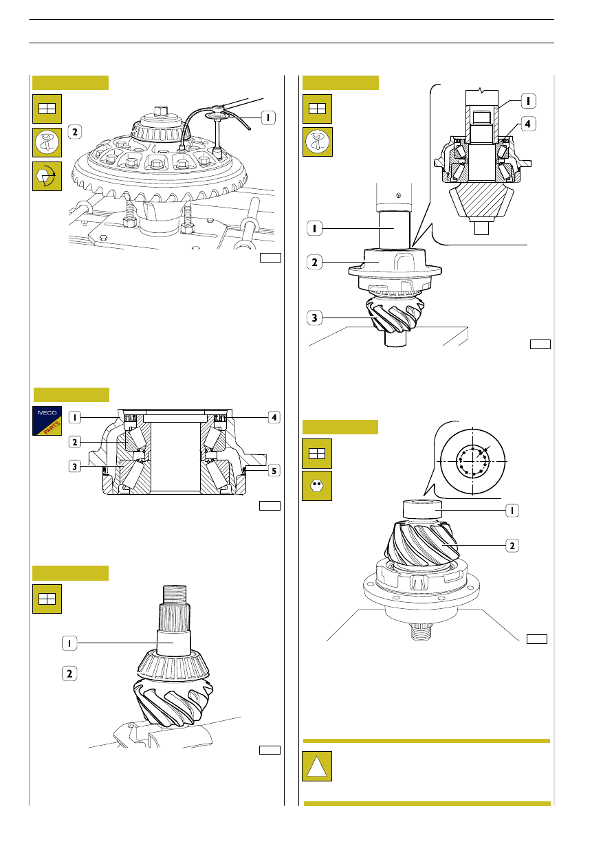
Figure 59
Figure 60
Figure 61
Figure 62
Figure 63
The bevel pinion mount (1) is supplied as a spare together with
the tapered roller bearings (2 and 3) and the seals (4 and 5).
Using a press and a suitable tube (1) positioned on the inner
ring of the roller bearing (4), fit the mount (2) on the bevel
pinion (3).
49236A
- 2
nd
phase: closing, with tool 99395216 (1) with an angle
of 80 to 90
°.
Heat the bearing (2) to a temperature of 100
°C for approx.
15 min. in an air circulation oven and drive it in with an
appropriate drift.
526249
FITTING THE MOUNT ON THE
BEVEL PINION
α
49237
Heat the bearing (2) to a temperature of 100
°C for 15 min.
in an air circulation oven and mount it on the bevel pinion
(1).
72768
Heat the bearing (1) to a temperature of 100
°C for 15 min.
in an air circulation oven and mount it on the bevel pinion
(2).
Lock the bearing by notching the bevel pinion at 10
equidistant points as shown in the figure. This should be done
conscientiously with a suitable punch.
!
The diameter of the impression has to be between
3.40 to 4.10 mm, corresponding to a depth of 0.30
to 0.44 mm respectively, using a load of 4000 kg with
a ball with a 10 mm diameter.
30
REAR AXLE MS 13-175
S
TRALIS
AT/AD
Base - January 2003