Engine Iveco Vector 8. Manual - part 30


  Index      Iveco     Engine Iveco Vector 8 - service repair manual 2006 year


Search            


Content   ..  28  29  30  31   ..


Engine Iveco Vector 8. Manual - part 30


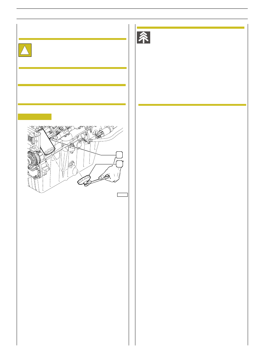
After positioning the tool (1) 99360091 under the filter,
unscrew and remove the filters (3 and 4) with the aid of a 27
mm wrench.

!

Handle all parts extremely carefully. Never get your
hands or fingers between pieces. Wear the required
safety clothing such as goggles, gloves, safety shoes
and helmet.

To change the fuel filters, proceed as illustrated here.

Before disassembling, place under the filter a basin
of suitable capacity.

Improper waste disposal is a threat for the
environment. Potentially hazardous waste used on
IVECO vehicles includes lubricants, fuels, coolants,
filters and batteries.

Use watertight containers when draining off
fluids. Never use containers for foodstuffs or
beverages that can lead people to drink from
them.

Never throw waste on the ground, on tips or
in water courses.

Obtain information on the appropriate ways
of recycling or disposing of waste from the
local authorities or collection centres.

Replace the filters with new parts, hand screw and tighten for
another 3/4 turn.

Figure 18

1

2

REPLACING DIESEL FILTER(S)
For applications DRAGON and GRIFFON

NOTE

103181

92

SECTION 3 - INDUSTRIAL APPLICATION

VECTOR 8 ENGINES

Base - April 2006

Print P2D32V001E

Figure 19

Figure 20

Figure 21

Figure 22

Figure 23

- Disconnect the power supply cables (1).

- Unscrew the cheese-headed screw M10x70 (3)

fastening the fixing bracket (4).

- Now fit on tool 99368505 (5) and, using the specific

wrench, completely remove the injector from its casing.

- Clean the injector seat.

- On completing these operations, fit the injector (7) back

on together with the fixing bracket (6).

!

Handle all parts extremely carefully.

Never get your hands or fingers between pieces.

Wear the required safety clothing such as goggles,
gloves, safety shoes and helmet

CHANGING AN INJECTOR

To change an injector, proceed as illustrated here:

- Disassemble the pipes (2) on the injector side and on the

flow limiting device side by means of wrench 99368506.

SECTION 3 - INDUSTRIAL APPLICATION

93

VECTOR 8 ENGINES

Print P2D32V001E

Base - April 2006

Figure 24

Figure 25

- Tight with a pre-torque of 20 Nm the fitting on both side,

flow-limiter and injector side. During the tightening
procedure the injector and the flow-limiter have to be
hold against the tighten direction.

- Tight with a final torque of 80±5 Nm the fitting on both

side, flow-limiter and injector side. During the tightening
procedure the injector and the flow-limiter have to be
hold against the tighten direction.

- Test engine for leak detection.

- Using the specific wrench, screw the cheese—headed

screw M10x70 back on to a tightening torque of 32

÷ 36

Nm.

!

Always change the O—ring in the assembly phase.
Lubricate the O—ring before installation (use
vaseline).

- Check the sealing surface of the leaking pipe and the

surface on the injector and flow limiter. Cleaning the
surfaces and remove dirt if necessary. In case the sealing
surface are damaged , replace the part.

- Lubricate with clean engine oil the fitting and the sealing

surface.

- Tight by hand the fitting on both side , flow-limiter and

injector side.

!

During positioning please clean well the spherical
surfaces and the Threaded part of pipe by dipping it
in a clean container filled with clean motor oil.

94

SECTION 3 - INDUSTRIAL APPLICATION

VECTOR 8 ENGINES

Base - April 2006

Print P2D32V001E

CHANGING BLOW-BY FILTER

Figure 26

The blow-by filter is positioned, by means of a support, to
the gearbox supporting bracket in front of the passenger cab
water/heating water heat exchanger.

The blow-by filters can only be replaced by taking the unit
apart completely and disassembling the same at the bench.

- Disconnect the inlet pipe (3) to the filter and the

condensed oil drain pipe (2) to the sump.

- Loosen the straps that retain the sleeves (4) for vapour

escape towards the outlets.

- Unscrew the screws (5) securing the filter on its bracket.

Improper waste disposal is a threat for the
environment. Potentially hazardous waste used on
IVECO vehicles includes lubricants, fuels, coolants,
filters and batteries.

Use watertight containers when draining off
fluids. Never use containers for foodstuffs or
beverages that can lead people to drink from
them.

Never throw waste on the ground, on tips or
in water courses.

Obtain information on the appropriate ways
of recycling or disposing of waste from the
local authorities or collection centres.

Support the blow-by filter to prevent sudden
disconnection.

- Loosen screws (5) on both sides, then separate the two

covers (4) from the filter (1) body.

- Take out the two filters (2), then replace them.

- Re-assemble the various parts after washing the body and

covers with a suitable detergent.

- After the filter has been fitted, place it into its own

housing on the support secured to the gearbox
supporting bracket.

Figure 27

Replace the gasket (3).

NOTE

NOTE

SECTION 3 - INDUSTRIAL APPLICATION

95

VECTOR 8 ENGINES

Print P2D32V001E

Base - April 2006


Content   ..  28  29  30  31   ..