Engines Iveco C87 / Cursor 87. Manual - part 27
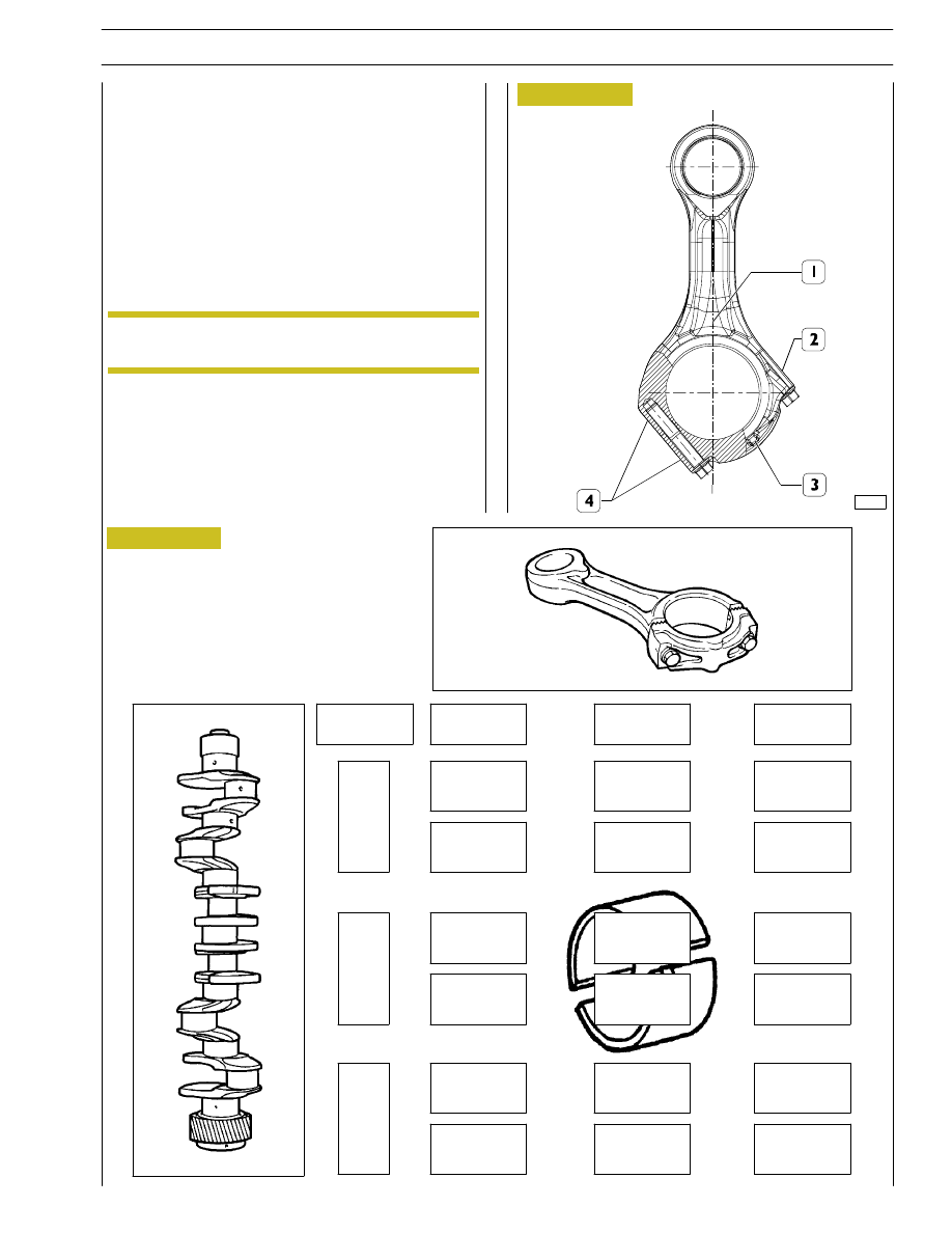
Figure 29
SELECTING THE BIG END BEARING SHELLS
(JOURNALS WITH NOMINAL DIAMETER)
There are 4 references on the connecting rod casing in the
positions illustrated:
1.
Coloured mark for identifying the weight
2.
Coloured mark for identifying the diameter grade
3.
Positioning stud visible from the front of the engine
4.
Progressive number for identifying the connecting rod
The number, indicating the class of diameter of the bearing
shell seat may be 1, 2 o 3.
Determine the type of big end bearing to fit on each journal
by following the indications in the table (Figure 30).
47557
STD.
1
2
3
green
green
red
green
red
red
red
green
green
yellow
yellow
yellow
green
green
yellow
green
green
green
Class
Figure 30
The identification colours of the marks are given in
the table on page 31.
NOTE
1
yellow
2
green
3
blue
SECTION 4 - OVERHAUL AND TECHNICAL SPECIFICATIONS
23
F2C CURSOR ENGINES