Engines Iveco C87 / Cursor 87. Manual - part 24
115882
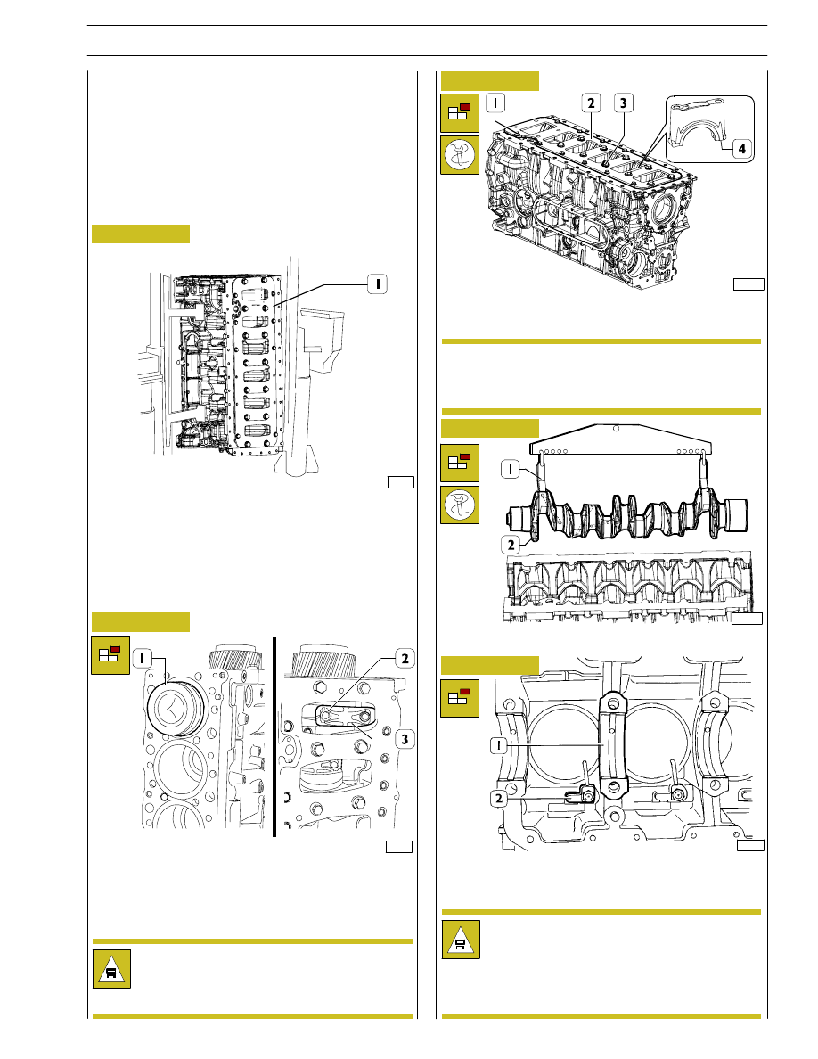
Figure 1
Figure 2
Figure 3
Figure 4
Untighten screws (2) fixing the connecting rod cap (3) and
remove it. Remove the connecting rod-piston (1) assembly
from the upper side.
Repeat these operations for the other pistons.
Use adequate hexagonal spanner, unlock screws (1 and 3)
and remove stiffening plate (2) as well as main journals (4).
115881
Rotate the block (1) to the vertical position.
Using tool 99360500 (1), remove the crankshaft (2).
Remove the main bearing shells (1), unscrew the screws and
take out the oil nozzles (2).
Remove the cylinder liners as described under the relevant
subheading on page 15.
After disassembling the engine, thoroughly clean
disassembled parts and check their integrity.
Instructions for main checks and measures are given
in the following pages, in order to determine
whether the parts can be re-used.
Keep the big end bearing shells in their respective
housings and/or note down their assembly position
since, if reusing them, they will need to be fitted in
the position found upon removal.
Note down the assembly position of the top and
bottom main bearing shells since, if reusing them, they
will need to be fitted in the position found upon
removal.
ENGINE OVERHAUL
ENGINE REMOVAL AT THE BENCH
The
following
instructions
are
prescribed
on
the
understanding that the engine has previously been placed on
the rotating bench and that removal of all specific
components of the equipment have been already removed
as well. (See Section 3 of the manual herein).
The section illustrates therefore all the most important
engine overhaul procedures.
47571
114615
NOTE
Figure 5
114035
SECTION 4 - OVERHAUL AND TECHNICAL SPECIFICATIONS
11
F2C CURSOR ENGINES